Lead-Acid Battery Charging Methods
Lead - Acid Batteries: Energy Conversion and Charging Methods
A lead - acid battery serves as a storage medium for chemical energy, which can be converted into electrical energy whenever needed. The process of transforming chemical energy into electrical energy is referred to as charging, while the reverse process, where electrical power is converted back into chemical energy, is known as discharging. During the charging phase, an electric current flows through the battery, driven by the underlying chemical reactions taking place within it. The lead - acid battery predominantly employs two primary charging techniques: constant voltage charging and constant current charging.
Constant Voltage Charging
Constant voltage charging stands as the most prevalent method for charging lead - acid batteries. This approach offers several advantages, such as reducing the overall charging time and enhancing the battery's capacity by up to 20%. However, it comes with a trade - off: a decrease in charging efficiency of approximately 10%.
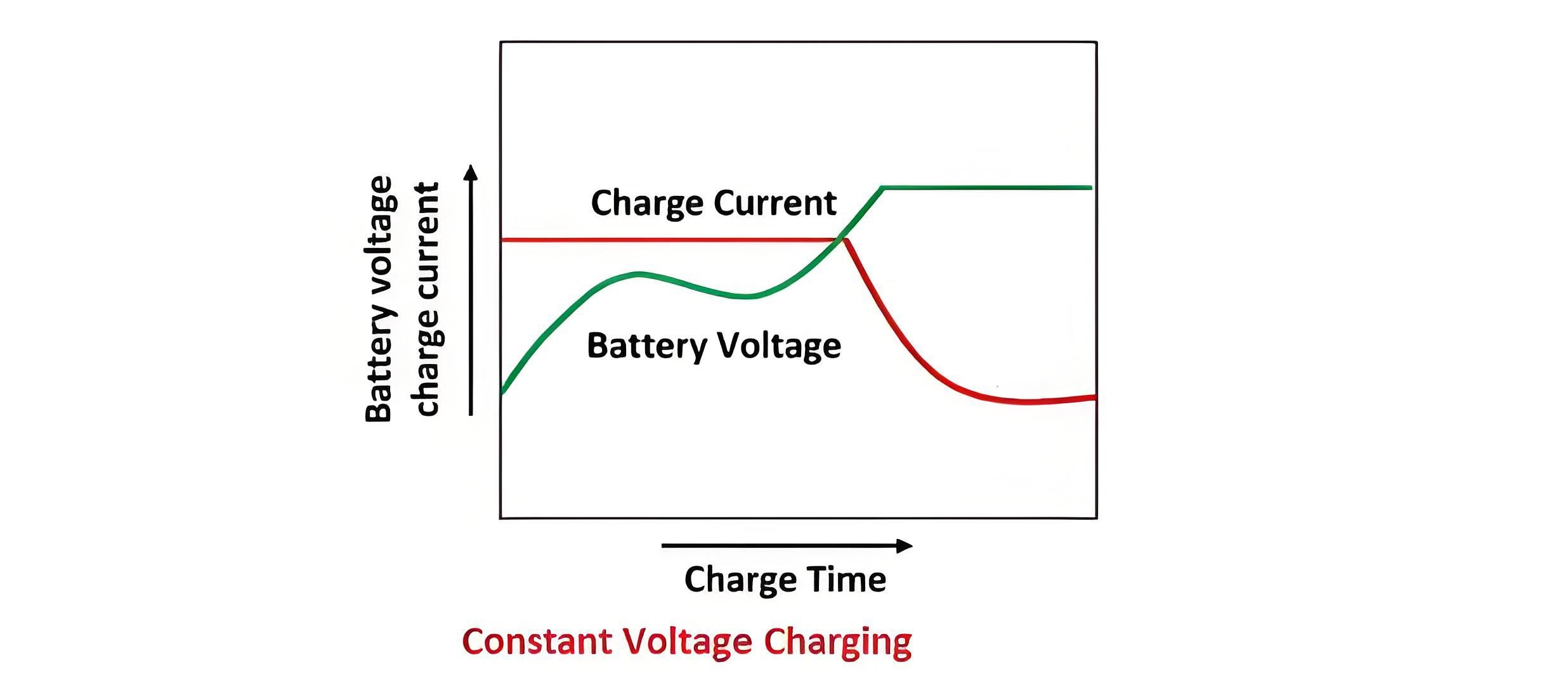
In the constant voltage charging method, the charging voltage remains fixed throughout the entire charging cycle. At the start of the process, when the battery is in a discharged state, the charging current is relatively high. As the battery accumulates charge, its back electromotive force (emf) increases. Consequently, the charging current gradually diminishes over time, as the battery approaches its fully charged state. This dynamic relationship between the charging voltage, current, and the battery's internal characteristics ensures that the battery is charged efficiently while minimizing the risk of overcharging or damage.
Advantages of Constant Voltage Charging
One of the key advantages of constant voltage charging is its flexibility in accommodating cells with varying capacities and different levels of discharge. This method allows for the simultaneous charging of multiple cells without the need for precise matching of their characteristics. Additionally, although the charging current is high at the beginning of the process, this high - current phase is relatively brief. As a result, it does not cause any significant damage to the cells, ensuring their longevity and safety.
As the charging process nears completion, the charging current gradually decreases and approaches zero. This occurs because the voltage of the battery eventually becomes almost equal to the voltage of the supply circuit, eliminating the potential difference that drives the current flow.
Constant Current Charging
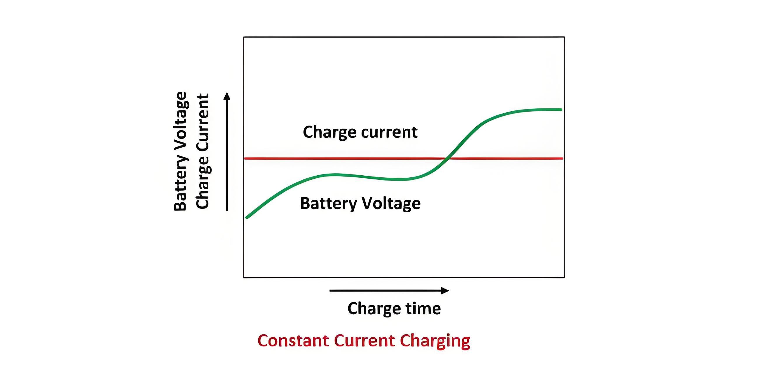
In the constant current charging method, batteries are connected in series to form groups. Each group is then connected to a direct - current (DC) supply main via loading rheostats. The number of batteries in each group is determined by the voltage of the charging circuit, with a requirement that the charging circuit voltage should not be less than 2.7 volts per cell.
Throughout the charging period, the charging current is maintained at a constant level. As the battery voltage increases during the charging process, the resistance in the circuit is reduced to ensure that the current remains unchanged. To prevent issues such as excessive gassing or overheating, the charging process is often carried out in two distinct steps. An initial phase involves charging the batteries with a relatively high current, followed by a finishing phase with a lower current, ensuring a more controlled and efficient charging cycle.
Details of Constant Current Charging Method
In the constant current charging approach, the charging current is typically set at around one - eighth of the battery's ampere rating. This specific current value helps ensure a balanced and safe charging process. As the battery charges, the excess voltage from the supply circuit is dissipated across the series resistance connected in the charging circuit.
When connecting battery groups for charging, careful consideration must be given to their configuration. The aim is to arrange the connections in a way that minimizes the energy consumption by the series resistance. This not only enhances the overall efficiency of the charging system but also reduces unnecessary power losses.
Regarding the series resistance itself, its current - carrying capacity is of critical importance. It must be equal to or greater than the required charging current. Failing to meet this requirement can lead to overheating of the resistance, which may ultimately cause it to burn out and disrupt the charging process.
Moreover, when selecting batteries for a charging group, it is essential that they have the same capacity. In cases where batteries of different capacities need to be charged together, they should be grouped and managed based on the least - capacity battery among them. This practice prevents issues such as overcharging or undercharging of individual batteries within the group, thereby safeguarding the performance and lifespan of each battery.
The Electricity Encyclopedia is dedicated to accelerating the dissemination and application of electricity knowledge and adding impetus to the development and innovation of the electricity industry.
