• Type 85C17 Analog Indicator Electrical Measuring Instrument
  • Type 85C17 Analog Indicator Electrical Measuring Instrument
  • Type 85C17 Analog Indicator Electrical Measuring Instrument
Type 85C17 Analog Indicator Electrical Measuring Instrument
$5.00
Model
85C17
Basic info
Brand Wone
Model NO. Type 85C17 Analog Indicator Electrical Measuring Instrument
type voltmeter
Input method DC
Series 85C17
Product Detail

Description

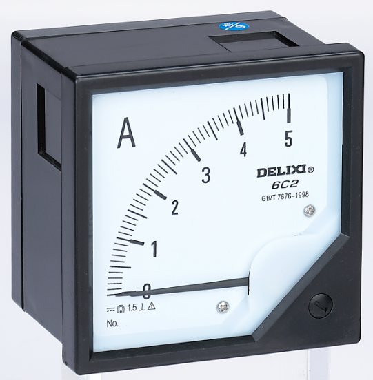
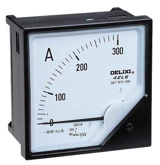
The fixed direct-acting analog indicator electric measuring instrument can display the change trend of the measurement, the reading is convenient, the cover is made of transparent plexiglass, and the card frame is installed.

The AC current and voltmeter in this series of instruments are suitable for measuring current and voltage in 50Hz AC circuitsMeasure; DC current and voltmeter are suitable for measuring current and voltage in DC circuits.In addition to separate use, it is mainly used for AC, DC transmission and distribution stations, power grids and other power systems and various switches Cabinets, power cabinets, control cabinets, compensation cabinets and other electrical devices are used as instrument panels

Industry applications

It is an important basis for the operation supervision of chemical power equipment by substation workers in the chemical industry, and can complete the acquisition and realization of basic data of power load statistics, production index calculation and technical material accumulation in chemical production. It is of great value for the stable and safe operation of the power system in chemical production.

In electrical measurement, the indication instrument of electrical measurement is an important part of the electrical measuring instrument, which can turn the measured electricity in the meter connected to the electrical measurement into a movable mechanical displacement, and can be directly read by the numerical value through the reaction of the mobile pointer connected to the scale . The abbreviation of the indicator instrument for electrical measurement is the indicator instrument, which can also be called the electrical and mechanical indicating instrument.

Features


  • The AC instrument adopts a magnetoelectric measuring mechanism and is equipped with an AC/DC measurement circuit to form a rectifier instrument. straight.

  • The flow meter consists of a magnetoelectric measuring mechanism and a measuring circuit.

Technical parameters

AC current, voltmeter range

Product type Unit Range
Access mode
AC meters A 0.05、0.1、0.2、0.3、0.5、2、2、3、5、7.5、10、15、20、30、50 Direct access
KA 1、2、3、5、7.5、10、 It is connected through a current transformer
V 3、5、7.5、10、15、20、30、50、60、75、100、120、150、200、250、300、450、500、600、 Direct access
KV 3.6、7.2、12、18、42、150、300、460
Access via external resistor

DC current, voltmeter range

DC current, voltmeter range Unit Range Access mode
DC meters mA 1、2、3、5、10、15、20、30、40、50、75、100、150、200、300、500 Direct access
A 1、2、3、5、7.5、10、15、20
5、7.5、10、30、30、50、75、100、150、200、300、500、750 Access via external shunt
KA 1、2、3、5、10 Direct access
V 3、5、7。5、10、15、20、30、50、60、75、100、120、150、200、250、300、450、500、600
KV 0.75、1、1.5 Access via external resistor

Dimensions

企业微信截图_17158387517386.png

Product show


091457126zxw.png

091457148fr7.png

201781893549334248.jpg


Know your supplier
Wone
Main Categories
High voltage/Low voltage/Wire cable/Instrument meters/New energy/Tester/Production equipment/Generator/Electrical fittings/Integrated Electrical Equipment
Business Type
Design/Manufacture/Sales
Highest Annual Export (USD)
$50,000,000
Professional Experience
1 years
Workplace
65666m²m²
占位
占位
Related Products
Related Knowledges
Failure Analysis and Design Optimization of Conventional Grounding Transformers
I. Core Cause of Damage: Electrodynamic Impact (Complying with GB/T 1094.5 / IEC 60076-5)The direct cause of high-voltage winding end collapse is the instantaneous electrodynamic impact induced by short-circuit current. When a single-phase grounding fault occurs in the system (such as lightning overvoltage, insulation breakdown, etc.), the grounding transformer, as the fault current path, withstands high-amplitude and steep-rise-rate short-circuit currents. According to Ampère's force law
Felix Spark
06/12/2025
Analysis of Grounding Transformer Operational Behavior Under System Single-Phase-to-Ground Fault Conditions
1 Theoretical AnalysisIn distribution networks, grounding transformers serve two key roles: powering low - voltage loads and connecting arc - suppression coils at neutrals for grounding protection. Grounding faults, the most common distribution network fault, heavily impact transformers’ operating characteristics, causing sharp changes in electromagnetic parameters and status.To study transformers’ dynamic behaviors under single - phase grounding faults, build this model: Assume a tr
Felix Spark
06/12/2025
Design Calculations for Neutral Grounding Schemes and Grounding Transformer Sizing in Utility-Scale Solar PV Plants
1 Classification of Neutral Grounding Methods for Solar Photovoltaic Power StationsInfluenced by differences in voltage levels and grid structures across regions, the neutral grounding methods of power systems are mainly categorized into non-effective grounding and effective grounding. Non-effective grounding includes neutral grounding via arc suppression coils and neutral ungrounded systems, while effective grounding comprises neutral solid grounding and neutral grounding via resistors. The sel
Dyson
06/12/2025
Zero-Sequence Impedance Characterization of Dry-Type Grounding Transformer with ZN Connection
In a neutral-insulated three-phase power system, an earthing transformer provides an artificial neutral point, which can be solidly earthed or earthed via reactors/arc suppression coils. The ZNyn11 connection is typical, where zero-sequence magnetomotive forces in the inner/outer half-windings of the same core column cancel out, balancing fault currents in series windings and minimizing zero-sequence leakage flux/impedance.Zero-sequence impedance is critical: it determines fault current magnitud
Dyson
06/12/2025
Case Analysis on Maloperation of Grounding Transformer Overcurrent Protection Relay
The neutral grounding mode refers to the connection between the power system neutral point and ground. In China's 35 kV and below systems, common methods include ungrounded neutral, arc-suppression coil grounding, and small-resistance grounding. The ungrounded mode is widely used as it allows short-term operation during single-phase grounding faults, while small-resistance grounding has become mainstream for its fast fault removal and overvoltage limitation. Many substations install grounding tr
Felix Spark
06/12/2025
Discussion on the Design of Low Zero-Sequence Impedance Grounding Transformers
With the expansion of power system scale and the cableization process of urban power grids, the capacitive current in 6kV/10kV/35kV power grids has significantly increased (generally exceeding 10A). As power grids at this voltage level mostly adopt neutral ungrounded operation mode, and the distribution voltage side of main transformers is usually in delta connection, lacking a natural grounding point, the arc during ground faults cannot be reliably extinguished, necessitating the introduction o
Dyson
06/11/2025
×
Inquiry
Download
Experts Electrical is dedicated to serving the personnel in the global power industry.
Join Experts Electrical, not only can you discover power equipment and power knowledge, but also canhnd like - minded friends!
商品视频播放