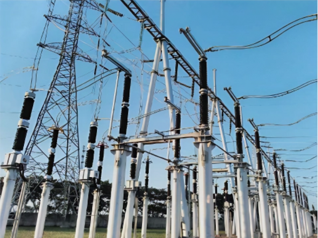
DS4C 252kV High voltage disconnect switch
discuss personally
Model
| Brand | ROCKWILL |
| Model NO. | DS4C 252kV High voltage disconnect switch |
| Rated voltage | 252kV |
| Rated normal current | 4000A |
| Rated frequency | 50/60Hz |
| Rated peak value withstand current | 125kA |
| Rated short-time withstand current | 50kA |
| Series | DS4C |
Product introduction:
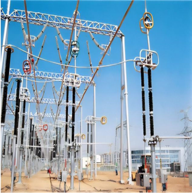
GW4C Switch Disconnector is a kind of outdoor HV electricity transmission equipment’s at three-phase AC frequency of 50Hz/60Hz. It is used for breaking or connecting HV lines under no loads so that these lines can be changed and connected and the way the electricity runs Is changed. In addition, It can be used lo exercise safe electrical insulation for such HV electric apparatuses as bus and breaker. The switch can open and close inductance/capacitance current and is able to open and close the bus to switch current.
This product has two insulators with horizontal center breaks. It Is openable In the middle and accessible to the grounding switch on one side or two sides. The disconnect switch adopts CS14G or CS11 manual operating mechanism or CJ2 motor-based operating mechanism to realize the tri-pole linkage,The earthing switch adopts CS14G manual operating mechanism to actual亿e tri-pole linkage
This product has been verified by the Chinese competent authority as having uniqueness in design and reaching intonational advanced level of similar products.
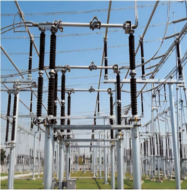
GW4C disconnect switch comprises three single poles and operating mechanism. Each single pole is made of a base, post insulator and conductive part revoting insulating posts are mounted at both sides of a long base. The conductive switch blade's contact arms are respectively fixed at the tops of the insulating posts.
When the Insulating post at one end of the actuator revolves to drive, and through the cross-over lever, brings the insulating post at the other end to rotate reversely by 90° to make the conductive switch blade circumgyrate. In this way, the isolating switch is opened and closed.
Main characteristic:
Main technical parameters:

Order notice:
Product model, rated voltage, rated current, Rated short-time withstand current and creepage distance must be specified at the goods-ordering time.
The disconnect switch offers several options of grounding (Left, right, both left and right).Unless otherwise specified, the goods supplied will be considered as providing the option of right grounding;
Note: