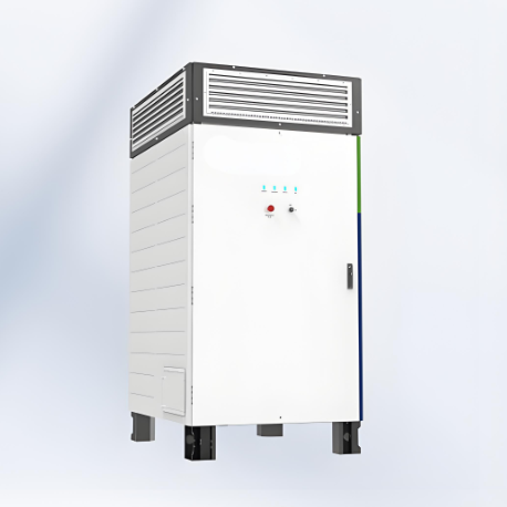
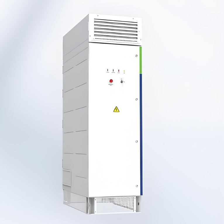
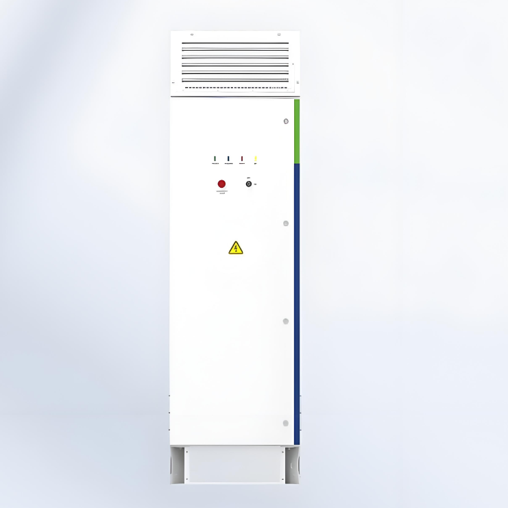
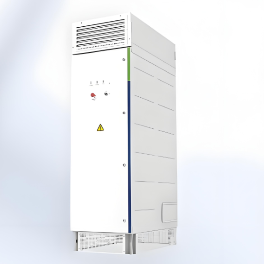
• Central Power Conversion System(PCS, 1500V)
  • Central Power Conversion System(PCS, 1500V)
  • Central Power Conversion System(PCS, 1500V)
Central Power Conversion System(PCS, 1500V)
discuss personally
Model
WN-1250-HB-UD
Basic info
Brand Wone
Model NO. Central Power Conversion System(PCS, 1500V)
Max.Efficiency 99%
AC output power 1250kVA
Max. DC voltage 1500V
Max. DC current 1403A
Max. AC output current 1046A
Series Power Conversion System
Product Detail

Features

  • Max. efficiency up to 99%.

  • Full reactive power four-quadrant capability.

  •  IP65 protection degree .

  • Black start ability.

  • Support VSG function.

  • Millisecond-level Power response to EMS/SCADA.

  • Three level topology.

  • Use alone or in combination with MV station.

DC Parameters:

image.png

AC parameters (On-Grid):

image.png

AC parameters (Off-Grid):

image.png

General data:

image.png

What is the VSG function of an energy storage converter?

The Basic Principles of Virtual Synchronous Generator (VSG)

  • Simulating the Behavior of Synchronous Generator:VSG technology enables the energy storage converter to simulate the dynamic characteristics of traditional synchronous generators, including inertial response, damping characteristics, and frequency regulation ability, through control algorithms.

  • Inertial Response:Synchronous generators possess mechanical inertia. When the grid frequency changes, the kinetic energy of the generator rotor can temporarily absorb or release energy, thus stabilizing the frequency. VSG simulates this inertial response by controlling the output power of the energy storage converter, enhancing the frequency stability of the grid.

  • Damping Characteristics:Synchronous generators have damping characteristics that can suppress frequency oscillations. VSG simulates this characteristic by introducing a damping control algorithm, further improving the stability of the system.

  • Frequency Regulation:VSG can actively participate in the frequency regulation of the grid. By adjusting the output power of the energy storage converter, it helps the grid to return to the rated frequency.


Know your supplier
Wone
Main Categories
High voltage/Low voltage/Wire cable/Instrument meters/New energy/Tester/Production equipment/Generator/Electrical fittings/Integrated Electrical Equipment
Business Type
Design/Manufacture/Sales
Highest Annual Export (USD)
$50,000,000
Professional Experience
1 years
Workplace
65666m²m²
占位
占位
Related Products
Related Knowledges
The design of the three-purpose grounding transformer
Underground Power Cable Transmission LinesDirect - buried power cable lines have large ground - distributed capacitance, causing high single - phase - to - ground short - circuit capacitive current. For 10 kV lines, if this current exceeds 10 A, arcs hardly self - extinguish, risking arc overvoltage and endangering line equipment. Arc extinction is thus necessary. With a Dyn - connected main transformer, an arc - suppression coil on the secondary neutral point suffices. For Yd - connected ones,
Dyson
06/12/2025
Failure Analysis and Design Optimization of Conventional Grounding Transformers
I. Core Cause of Damage: Electrodynamic Impact (Complying with GB/T 1094.5 / IEC 60076-5)The direct cause of high-voltage winding end collapse is the instantaneous electrodynamic impact induced by short-circuit current. When a single-phase grounding fault occurs in the system (such as lightning overvoltage, insulation breakdown, etc.), the grounding transformer, as the fault current path, withstands high-amplitude and steep-rise-rate short-circuit currents. According to Ampère's force law
Felix Spark
06/12/2025
Analysis of Grounding Transformer Operational Behavior Under System Single-Phase-to-Ground Fault Conditions
1 Theoretical AnalysisIn distribution networks, grounding transformers serve two key roles: powering low - voltage loads and connecting arc - suppression coils at neutrals for grounding protection. Grounding faults, the most common distribution network fault, heavily impact transformers’ operating characteristics, causing sharp changes in electromagnetic parameters and status.To study transformers’ dynamic behaviors under single - phase grounding faults, build this model: Assume a tr
Felix Spark
06/12/2025
Design Calculations for Neutral Grounding Schemes and Grounding Transformer Sizing in Utility-Scale Solar PV Plants
1 Classification of Neutral Grounding Methods for Solar Photovoltaic Power StationsInfluenced by differences in voltage levels and grid structures across regions, the neutral grounding methods of power systems are mainly categorized into non-effective grounding and effective grounding. Non-effective grounding includes neutral grounding via arc suppression coils and neutral ungrounded systems, while effective grounding comprises neutral solid grounding and neutral grounding via resistors. The sel
Dyson
06/12/2025
Zero-Sequence Impedance Characterization of Dry-Type Grounding Transformer with ZN Connection
In a neutral-insulated three-phase power system, an earthing transformer provides an artificial neutral point, which can be solidly earthed or earthed via reactors/arc suppression coils. The ZNyn11 connection is typical, where zero-sequence magnetomotive forces in the inner/outer half-windings of the same core column cancel out, balancing fault currents in series windings and minimizing zero-sequence leakage flux/impedance.Zero-sequence impedance is critical: it determines fault current magnitud
Dyson
06/12/2025
Case Analysis on Maloperation of Grounding Transformer Overcurrent Protection Relay
The neutral grounding mode refers to the connection between the power system neutral point and ground. In China's 35 kV and below systems, common methods include ungrounded neutral, arc-suppression coil grounding, and small-resistance grounding. The ungrounded mode is widely used as it allows short-term operation during single-phase grounding faults, while small-resistance grounding has become mainstream for its fast fault removal and overvoltage limitation. Many substations install grounding tr
Felix Spark
06/12/2025
×
Inquiry
Download
Experts Electrical is dedicated to serving the personnel in the global power industry.
Join Experts Electrical, not only can you discover power equipment and power knowledge, but also canhnd like - minded friends!
商品视频播放