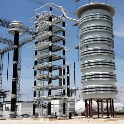
6kV 10kV Series air-core current-limiting reactor
discuss personally
Model
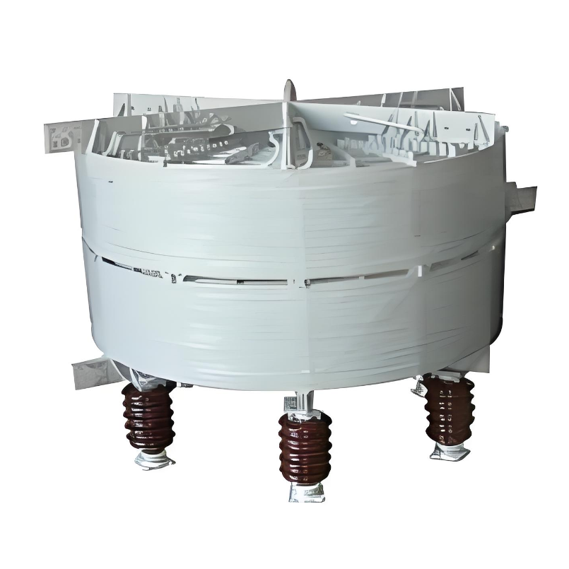
| Brand | Wone |
| Model NO. | Series air-core current-limiting reactor |
| Rated voltage | 10kV |
| Rated normal current | 200A |
| Reactance | 4% |
| Series | XKGKL |
Description:
The current-limiting reactor is connected in series with the power system to limit the short-circuit current when the power system fails. When a short circuit occurs in the line, the current-limiting reactor uses its reactor characteristics to limit the short-circuit current of the line within a certain limit, so as to facilitate the smooth and effective removal of the fault of the switchgear. Current-limiting reactors generally use air-core reactors with good linearity of reactance values. The current-limiting reactor can operate safely and reliably at long-term rated current. In the case of failure, the ampere turns increase by several times or dozens of times, but its resistance value or the ability to limit the short-circuit current cannot be reduced, so the current-limiting reactor should be made into a hollow product rather than an iron-core product.
Feature:
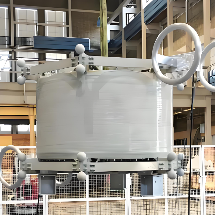
Multi-layer parallel air duct structure, epoxy glass fiber wrapping, uniform impact potential distribution, good ability to withstand short-circuit current.
Using computer-aided design, the structure and parameters of the product can be quickly and accurately determined according to the customer's requirements.
The dry hollow form makes up for the disadvantages of oil leakage in the oil-immersed reactor, and there is no concern about core saturation, and the inductance value is linear.
The winding is wound with a variety of small cross-section film-wrapped wires, which has the characteristics of excellent insulation performance, low loss, light weight, small size, and maintenance-free.
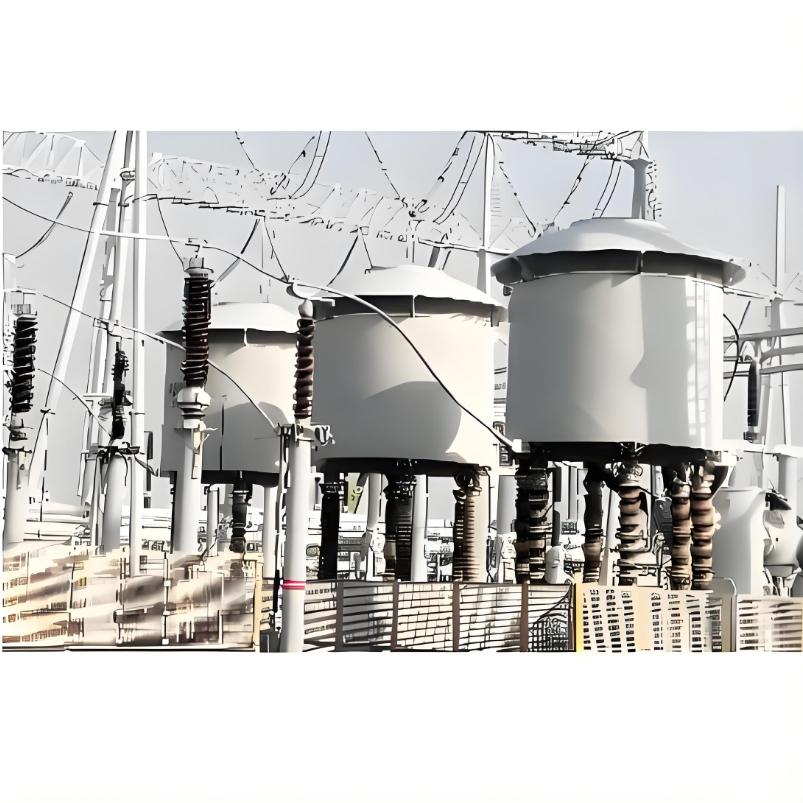
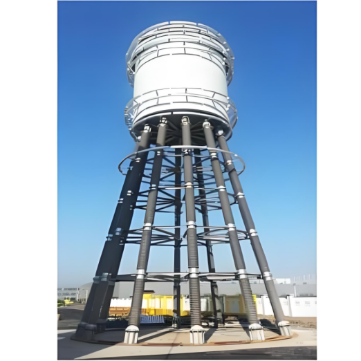
The entire outer surface of the reactor is coated with an anti-ultraviolet protective layer, which can be used indoors and outdoors, and the installation method is flexible, which can be stacked in three phases or arranged horizontally in three phases.
Technical indicators:
The parameters of rated voltage, rated current and supporting capacitors are shown in the technical parameter table.
Overload capacity: 1.35 times the rated current for continuous operation.
Thermal stability: It can withstand the rated current at the last of the rated reactance rate for 2s.
Dynamic stability performance: It can withstand 2.55 times of thermal stability current, time 0.5s, and no thermal mechanical damage.
Temperature rise: the average temperature rise of the coil is ≤ 75k (resistance method).
Parameters:
Insulation Level: LI60AC35, LI75AC42


What is the current limiting principle based on inductance of series air-core current limiting reactors?
Current Limiting Principle Based on Inductance:
According to Faraday's law of electromagnetic induction, when current flows through the windings of a reactor, it generates a magnetic field around the windings. This magnetic field, in turn, opposes the change in current, as described by Lenz's Law.
A series-connected air-core current-limiting reactor utilizes this principle. When a short-circuit fault or an excessive current occurs in the circuit, the inductance of the reactor impedes the rapid rise of the current, limiting its magnitude. This protects other equipment in the circuit from the impact of high currents.
For example, in a power transmission system, if a short circuit occurs on a line, the series-connected air-core current-limiting reactor will quickly increase the impedance of the circuit, preventing the short-circuit current from reaching excessively high values instantaneously. This provides additional time for protective devices, such as circuit breakers, to operate, ensuring the safety and stability of the system.