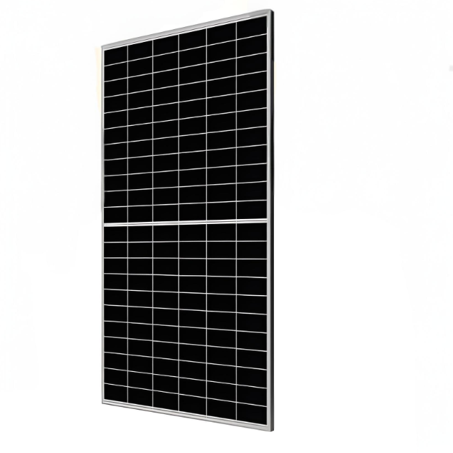
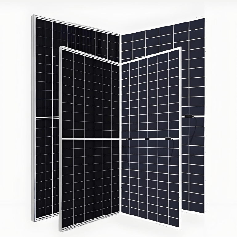
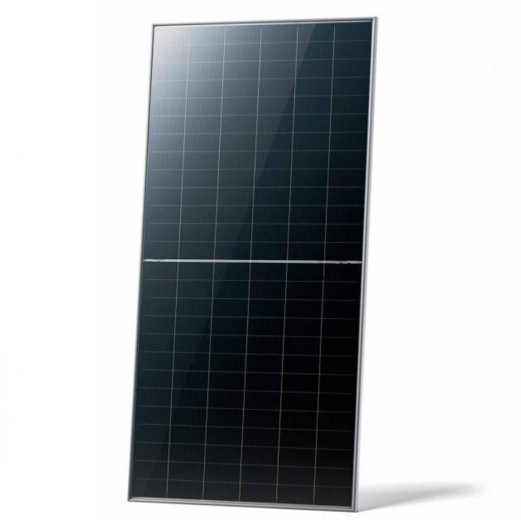
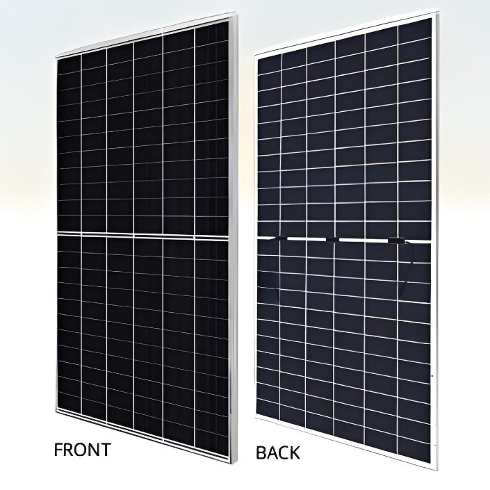
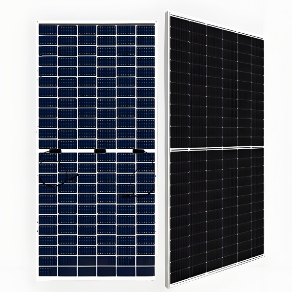
640 W - 670 W Bifacial high-power Dual cell PERC module (mono)
discuss personally
Model
| Brand | Wone |
| Model NO. | 640 W - 670 W Bifacial high-power Dual cell PERC module (mono) |
| Power Bifaciality | 70% |
| Max. System Voltage | 1500V (IEC) |
| Max. Series Fuse Rating | 35 A |
| Module Fire Performance | CLASS C |
| Max. power of the module | 670 W |
| Max. efficiency of Module | 21.6 % |
| Series | Bifacial MONO PERC |
Features
Module power up to 670 W Module efficiency up to 21.6 %.
Up to 8.9 % lower LCOE Up to 4.6 % lower system cost.
Comprehensive LID / LeTID mitigation technology, up to 50% lower degradation.
Compatible with mainstream trackers, cost effective product for utility power plant.
Better shading tolerance.
Standard
40 °C lower hot spot temperature, greatly reduce module failure rate.
Minimizes micro-crack impacts.
Heavy snow load up to 5400 Pa, wind load up to 2400 Pa*.
Engineering drawing(mm)

CS7N-650MB-AG / I-V gurves

Electrical date/STC*

Electrical date/NMOT*

Electrical date

Mechanical charactheristics

Temperature characteristics

What is LCOE?
LCOE (Levelized Cost of Energy) refers to the levelized cost of electricity. It is a method used to evaluate the average cost of a power plant throughout its entire life cycle. LCOE takes into account all the expenses of the power plant's construction and operation and apportions them to each unit of electricity produced, thereby measuring the economic viability of a power generation project.
Calculation Formula:
The basic calculation formula for LCOE is as follows:
LCOE = Present Value of Total Costs / Present Value of Total Electricity Generation
Among them, the "Present Value of Total Costs" includes the sum of all costs after discounting, such as construction costs, operation and maintenance costs, fuel costs, decommissioning costs, etc.; the "Present Value of Total Electricity Generation" is the value after discounting of the total electricity generated by the power plant throughout its entire life cycle.