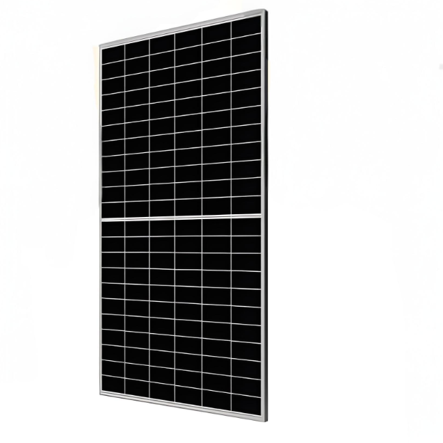
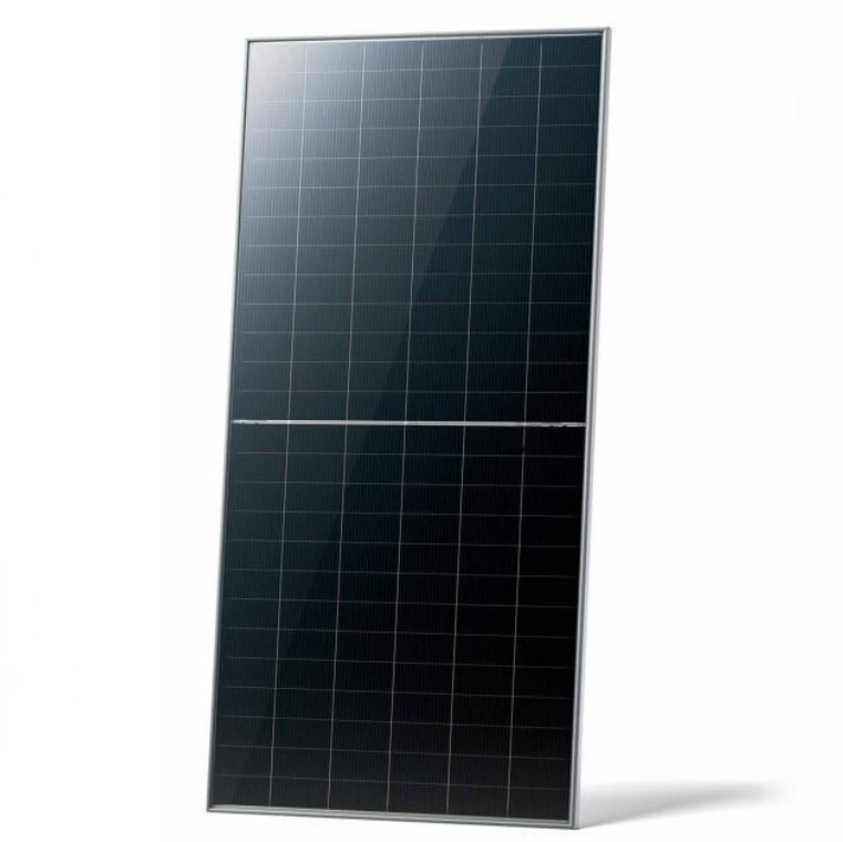
625-650 Watt bifacial module with dual glass
discuss personally
Model
| Brand | Wone |
| Model NO. | 78HL4-BDV 625-650 Watt BIFACIAL MODULE WITH DUAL GLASS |
| Maximum Power | 640Wp |
| Series | 78HL4-BDV |
Certification
IEC61215:2021 / IEC61730:2023 ·
IEC61701 / IEC62716 / IEC60068 / IEC62804 ·
ISO9001:2015: Quality Management System ·
ISO14001:2015: Environment Management System ·
ISO45001:2018: Occupational health and safety management systems.
Features
N-type modules with Tunnel Oxide Passivating Contacts (TOPcon) technology offer lower LID/LeTID degradation and better low light performance.
N-type modules with JinkoSolar's HOT 3.0 technology offer better reliability and efficiency.
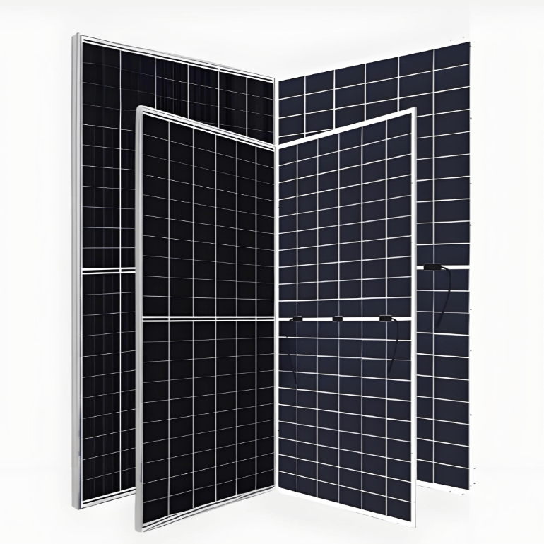
Dual-sided power generation gain increases with backside exposure to light, significantly reducing LCOE.
Certified to withstand: 5400 Pa front side max static test load 2400 Pa rear side max static test load.
Better light trapping and current collection to improve module power output and reliability.
Minimizes the chance of degradation caused by PID phenomena through optimization of cell production technology and material control.

Mechanical Characteristics

Packaging Configuration

Specifications (STC)

Specifications (BNPI)

Application Conditions

Engineering Drawings

*Note: For specific dimensions and tolerance ranges, please refer to the corresponding detailed module drawings.
Electrical Performance & Temperature Dependence


What is a solar bifacial module?
Solar bifacial modules are solar panels capable of absorbing light from both sides (that is, the front and the back) and converting it into electrical energy. Compared to traditional monofacial solar modules, bifacial modules have a higher potential for energy output, as they can not only capture the sunlight directly shining on them but also absorb light reflected from the ground as well as scattered light from the surroundings.
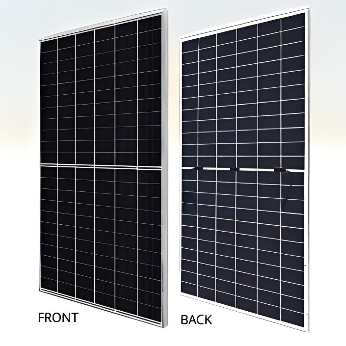
Working Principle of Bifacial Modules:
Front Side Absorption: The front side works like traditional solar modules, absorbing direct sunlight through the solar cells and converting it into electrical energy.
Back Side Absorption: The back side is also covered with a layer of solar cells that can absorb sunlight reflected from the ground as well as scattered light from the surroundings.
Light Trapping: The reflectivity of the ground affects the power generation efficiency of the back side of bifacial modules. Ground surfaces that are white or light in color have higher reflectivity, providing more reflected light to the solar cells on the back side.
Environmental Impact: The installation environment can also affect the performance of bifacial modules. For example, different surfaces such as grasslands, snow-covered areas, or rooftops will have varying levels of reflectivity and amounts of scattered light.