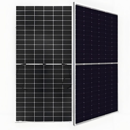
600 W ~ 630 W High-power N-type TOPCON bifacial modules
discuss personally
Model
| Brand | RW Energy |
| Model NO. | 600 W ~ 630 W High-power N-type TOPCON bifacial modules |
| Power Bifaciality | 80% |
| Max. System Voltage | 1500V (IEC) |
| Max. Series Fuse Rating | 35 A |
| Module Fire Performance | CLASS C |
| Max. power of the module | 630W |
| Max. efficiency of Module | 22.2% |
| Series | N-type Bifacial TOPCon Technology |
Features
Module power up to 630 W Module efficiency up to 23.3 %.
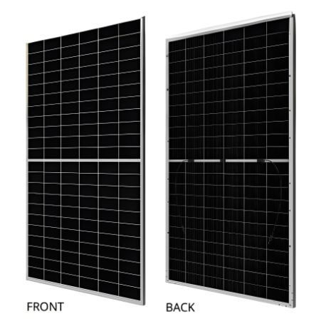
Up to 85% Power Bifaciality, more power from the back side.
Excellent anti-LeTID & anti-PID performance. Low power degradation, high energy yield.
Lower temperature coefficient (Pmax): -0.29%/°C, increases energy yield in hot climate.
Lower LCOE & system cost.
Standard
Tested up to ice ball of 35 mm diameter according to IEC 61215 standard.
Minimizes micro-crack impacts.
Heavy snow load up to 5400 Pa, wind load up to 2400 Pa*.
Engineering drawing(mm)

CS6.2-66TB-610 / I-V gurves

Electrical date/STC*

Electrical date/NMOT*

Electrical date

Charactheristics date

Temperature characteristics

What is bifacial gain in PV modules?
Definition:
The maximum power bifaciality ratio refers to the ratio of the maximum power that can be generated on the back side of a bifacial photovoltaic module to the maximum power on the front side under standard test conditions (Standard Test Conditions, STC). It is a percentage value used to quantify the contribution degree of the power generation capacity on the back side of the bifacial module relative to that on the front side.
Calculation Formula:
The maximum power bifaciality ratio can be expressed by the following formula:
Maximum Power Bifaciality Ratio (%) = (Maximum Power on the Back Side / Maximum Power on the Front Side) × 100%
Here, "Maximum Power on the Back Side" refers to the maximum power that can be generated on the back side of the bifacial photovoltaic module under standard test conditions; "Maximum Power on the Front Side" refers to the maximum power that can be generated on the front side under the same conditions.