| Brand | Vziman |
| Model NO. | 6.6kV Three-phase Power Distribution Transformer |
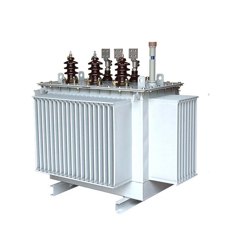
| Rated capacity | 1500kVA |
| Voltage grade | 6.6KV |
| Series | Distribution Transformer |
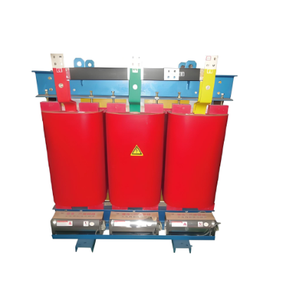
Product overview:
High reliability of operation verification in more than 50 countries and regions around the world.
Mainly used in power generation enterprises, industrial and mining enterprises, water conservancy facilities, petrochemical enterprises 6.6 kV power distribution system.
Products are mainly exported to southeast Asia, East Asia, Central Asia and other developing countries and regions.
Standards: IEC 60076 series, IEC 6013, IEC 60214-1, IEC 60296; GB1094 series, GB/T6451-2015, GB/T7597-2007, etc.
Product advantages
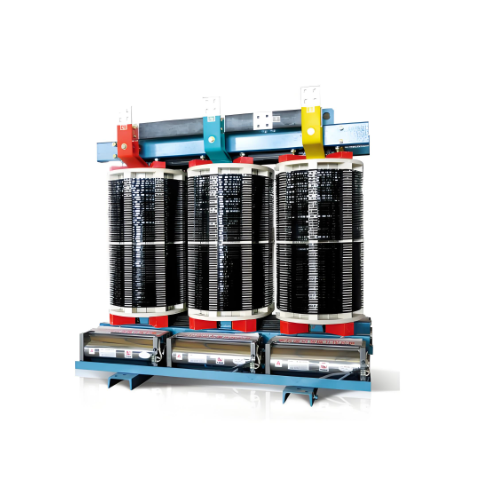
Leading technology:
High pressure copper tape winding technology, improve lightning resistance.
Low voltage copper foil winding technology, high quality A class insulation material insulation.
Small magnetic leakage, high mechanical strength, strong short circuit resistance.
Iron core 45° full oblique joint step laminated structure.
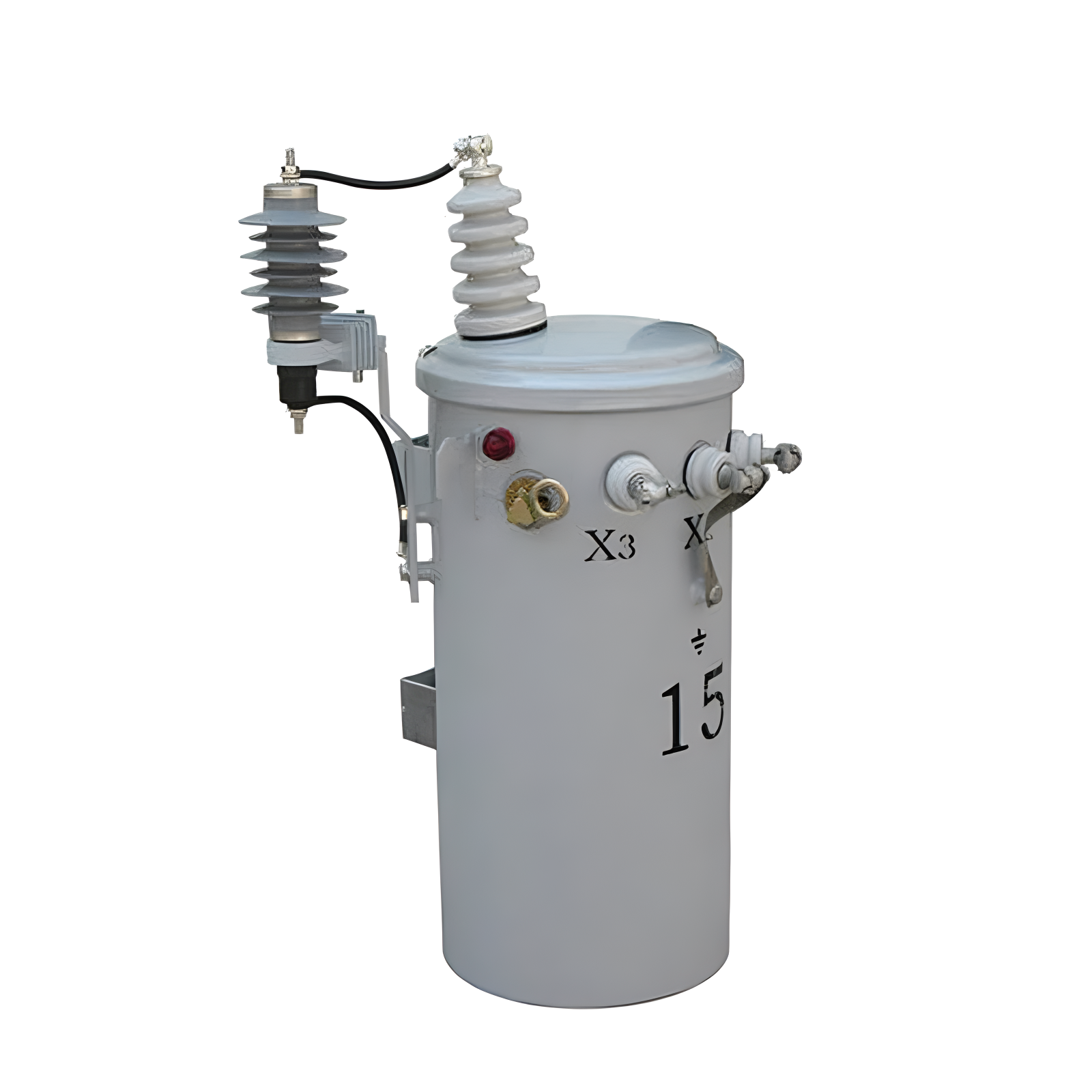
The shell:
Mitsubishi laser cutting machine and CNC punching, reducing, folding and other equipment to ensure the accuracy of processing.
ABB robot automatic welding, laser detection, to avoid leakage, qualified rate of 99.99998%.
Electrostatic spray treatment, 50 years of paint (coating corrosion resistance within 100h, hardness ≥0.4.
Fully sealed structure, maintenance-free and maintenance-free, normal operation life of more than 30 years.
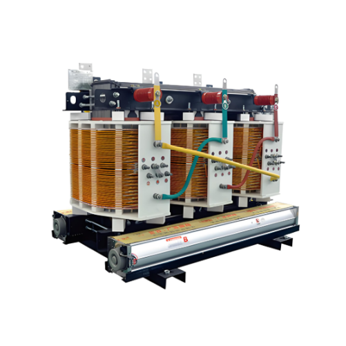
The iron core
The core material is high quality cold rolled grain oriented silicon steel sheet with mineral oxide insulation (from Baosteel, Wisco, China).
Minimize loss level, no-load current and noise by controlling the cutting and stacking process of silicon steel sheet.
The iron core is specially reinforced to ensure the transformer structure is firm during normal operation and transportation.
winding:
Low voltage winding is made of high quality copper foil, excellent insulation resistance.
The high voltage windings are usually made of insulated copper wire, using the patented technology of Hengfengyou Electric.
Very good resistance to radial stress caused by short circuit.
High quality material:
Baowu Steel Group production of silicon steel sheet.
High quality anaerobic copper from China.
CNPC (Kunlun Petroleum) High quality transformer oil (25# 40#).
Other instructions:
The low-voltage outgoing terminal is tinned copper bar.
The high-voltage outlet terminals are ring tinned bolts.
Default no-load voltage regulation (on-load voltage regulation can be customized) Tap switch 5 or 7 speed adjustment.
Transformers above 630KVA are protected by gas relays.
Ordering instructions:
Main parameters of transformer (voltage, capacity, loss and other main parameters.
Transformer operating environment (altitude, temperature, humidity, location, etc.
Other customization requirements (tap switch, color, oil pillow, etc.
The minimum order quantity is 1 sets, worldwide delivery within 7 days.
Normal delivery period of 30 days, worldwide fast delivery.
How to choose the parameters of three-phase distribution transformer?
Main Parameters of a Transformer
Rated Capacity:
Definition: The rated capacity of a transformer is the apparent power it can output under rated operating conditions. The unit is kilovolt-amperes (kVA) or megavolt-amperes (MVA).
Common Values: For a common 6.6 kV three-phase distribution transformer, the rated capacities include 100 kVA, 200 kVA, 315 kVA, 400 kVA, 500 kVA, 630 kVA, etc.
Definition: Rated voltage includes the rated voltage on the high-voltage side and the rated voltage on the low-voltage side.
Example: For a 6.6 kV transformer, 6.6 kV is the rated voltage on the high-voltage side. The rated voltage on the low-voltage side is typically 0.4 kV or 0.69 kV, depending on the user's requirements.
Definition: Short-circuit impedance is an important parameter of a transformer, indicating the impedance of the transformer under short-circuit conditions. The size of the short-circuit impedance affects the short-circuit current and the voltage drop during a short circuit, which is significant for the protection and operational stability of the transformer.
Definition: No-load loss is the power consumed by the transformer when it is in a no-load state (i.e., the secondary side is open). It primarily includes hysteresis losses and eddy current losses in the core, as well as resistance losses in the windings. The smaller the no-load loss, the higher the efficiency of the transformer.
Definition: Load loss is the power consumed by the transformer when it is in a loaded state (i.e., the secondary side is connected to a load). It primarily includes resistance losses in the windings and additional losses due to leakage flux. Load loss is proportional to the square of the load current and is an important indicator of transformer performance.
This translation provides a clear and concise explanation of the main parameters of a transformer, including rated capacity, rated voltage, short-circuit impedance, no-load loss, and load loss.