• 5KW PC/PW PLUS PV inverter
5KW PC/PW PLUS PV inverter
$2400.00
Model
PVINV-5000
PVINV-5000S
Basic info
Brand Wone
Model NO. PC/PW PLUS PV inverter
Mounting type Wall-mounted
Rated Output Rating 5kW
Input Voltage DC48V
Rated PV input power 5.5kW
Series PC/PW PLUS
Product Detail

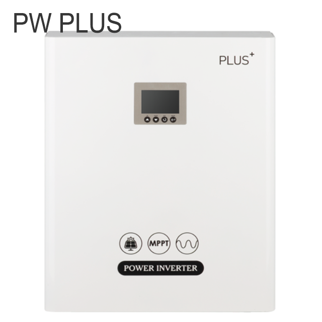
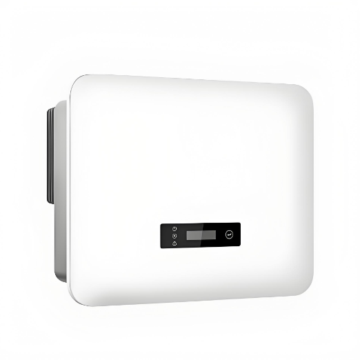
Photovoltaic inverter

PCW-en.png

Peculiarity

♦ Dual phase inverter.

♦ Up to 9 parallel machines, the output power can reach 45KW.

♦ Three parallel machines can be set up three-phase power supply

♦ Backward compatible with traditional lead batteries, colloidal batteries.

♦ The panel integrates a variety of interfaces, supporting a variety of protocols of the host computer and battery pack.

♦ Integrated MPPT, maximize the press of the remaining power of the photovoltaic panel.

♦ Highly integrated, feature-rich, one machine at most.

♦ PC PLUS-5 Standard 4U rack specifications.

♦ Can be customized adjustment management battery charging and discharging strategy.

♦ Modular design, easy maintenance.

Technical parameter

image.png

image.png

How does a PV inverter work?

A photovoltaic (PV) inverter is a high-performance device that primarily converts the direct current (DC) generated by solar panels into alternating current (AC).

  • DC Input: The DC power produced by solar panels is connected to the inverter's input via cables.

  • Maximum Power Point Tracking (MPPT): The inverter incorporates Maximum Power Point Tracking technology, which dynamically adjusts the input voltage and current to ensure the maximum energy output under varying light conditions.

  • DC Boost: If the input DC voltage is too low, the inverter has a boosting circuit to raise the voltage to the required level.

  • Pulse Width Modulation (PWM): PWM technology is used to generate an AC waveform that approximates a sine wave. The power electronic devices inside the inverter, such as IGBTs or MOSFETs, switch on and off according to certain rules to produce AC.

  • AC Output: The generated AC power is filtered to remove high-frequency noise and is stabilized through voltage regulation circuits to ensure stable output voltage and frequency.

  • Grid-Tie Function: For grid-tied inverters, the output AC power can be fed directly into the electrical grid for residential or commercial use.


Know your supplier
Wone
Main Categories
High voltage/Low voltage/Wire cable/Instrument meters/New energy/Tester/Production equipment/Generator/Electrical fittings/Integrated Electrical Equipment
Business Type
Design/Manufacture/Sales
Highest Annual Export (USD)
$50,000,000
Professional Experience
1 years
Workplace
65666m²m²
占位
占位
Related Products
Related Knowledges
The design of the three-purpose grounding transformer
Underground Power Cable Transmission LinesDirect - buried power cable lines have large ground - distributed capacitance, causing high single - phase - to - ground short - circuit capacitive current. For 10 kV lines, if this current exceeds 10 A, arcs hardly self - extinguish, risking arc overvoltage and endangering line equipment. Arc extinction is thus necessary. With a Dyn - connected main transformer, an arc - suppression coil on the secondary neutral point suffices. For Yd - connected ones,
Dyson
06/12/2025
Failure Analysis and Design Optimization of Conventional Grounding Transformers
I. Core Cause of Damage: Electrodynamic Impact (Complying with GB/T 1094.5 / IEC 60076-5)The direct cause of high-voltage winding end collapse is the instantaneous electrodynamic impact induced by short-circuit current. When a single-phase grounding fault occurs in the system (such as lightning overvoltage, insulation breakdown, etc.), the grounding transformer, as the fault current path, withstands high-amplitude and steep-rise-rate short-circuit currents. According to Ampère's force law
Felix Spark
06/12/2025
Analysis of Grounding Transformer Operational Behavior Under System Single-Phase-to-Ground Fault Conditions
1 Theoretical AnalysisIn distribution networks, grounding transformers serve two key roles: powering low - voltage loads and connecting arc - suppression coils at neutrals for grounding protection. Grounding faults, the most common distribution network fault, heavily impact transformers’ operating characteristics, causing sharp changes in electromagnetic parameters and status.To study transformers’ dynamic behaviors under single - phase grounding faults, build this model: Assume a tr
Felix Spark
06/12/2025
Design Calculations for Neutral Grounding Schemes and Grounding Transformer Sizing in Utility-Scale Solar PV Plants
1 Classification of Neutral Grounding Methods for Solar Photovoltaic Power StationsInfluenced by differences in voltage levels and grid structures across regions, the neutral grounding methods of power systems are mainly categorized into non-effective grounding and effective grounding. Non-effective grounding includes neutral grounding via arc suppression coils and neutral ungrounded systems, while effective grounding comprises neutral solid grounding and neutral grounding via resistors. The sel
Dyson
06/12/2025
Zero-Sequence Impedance Characterization of Dry-Type Grounding Transformer with ZN Connection
In a neutral-insulated three-phase power system, an earthing transformer provides an artificial neutral point, which can be solidly earthed or earthed via reactors/arc suppression coils. The ZNyn11 connection is typical, where zero-sequence magnetomotive forces in the inner/outer half-windings of the same core column cancel out, balancing fault currents in series windings and minimizing zero-sequence leakage flux/impedance.Zero-sequence impedance is critical: it determines fault current magnitud
Dyson
06/12/2025
Case Analysis on Maloperation of Grounding Transformer Overcurrent Protection Relay
The neutral grounding mode refers to the connection between the power system neutral point and ground. In China's 35 kV and below systems, common methods include ungrounded neutral, arc-suppression coil grounding, and small-resistance grounding. The ungrounded mode is widely used as it allows short-term operation during single-phase grounding faults, while small-resistance grounding has become mainstream for its fast fault removal and overvoltage limitation. Many substations install grounding tr
Felix Spark
06/12/2025
×
Inquiry
Download
Experts Electrical is dedicated to serving the personnel in the global power industry.
Join Experts Electrical, not only can you discover power equipment and power knowledge, but also canhnd like - minded friends!
商品视频播放