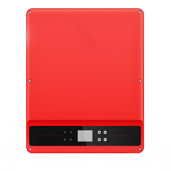
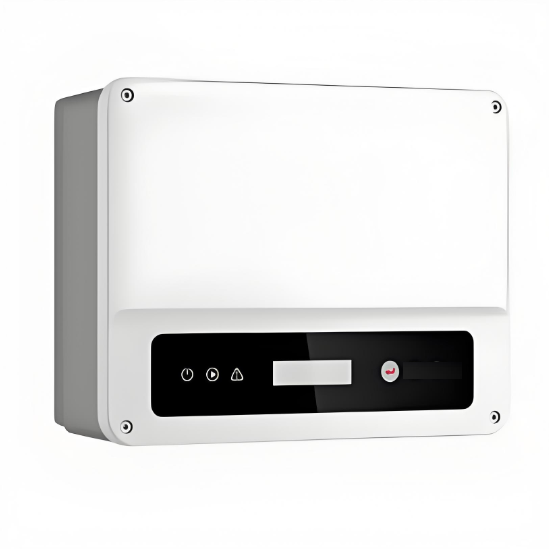
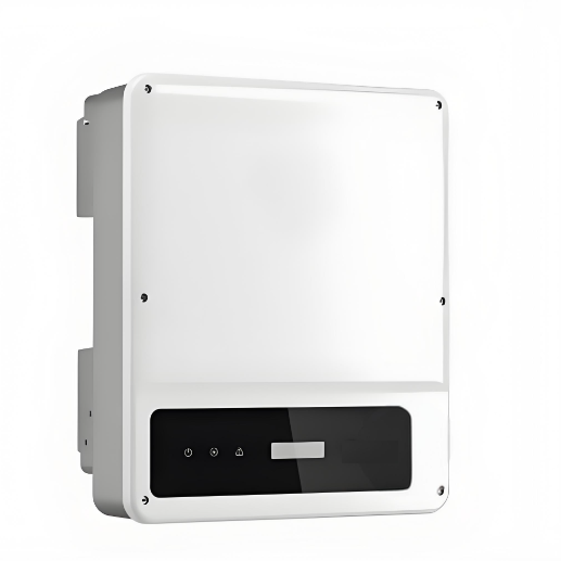
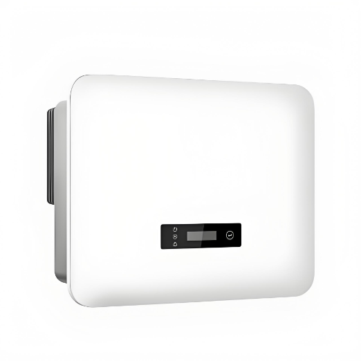
3.2KW 5KW 8KW 11KW PC/PW PV inverter
$4800.00
Model
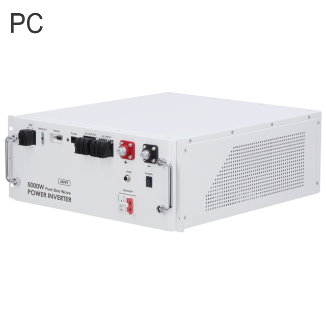
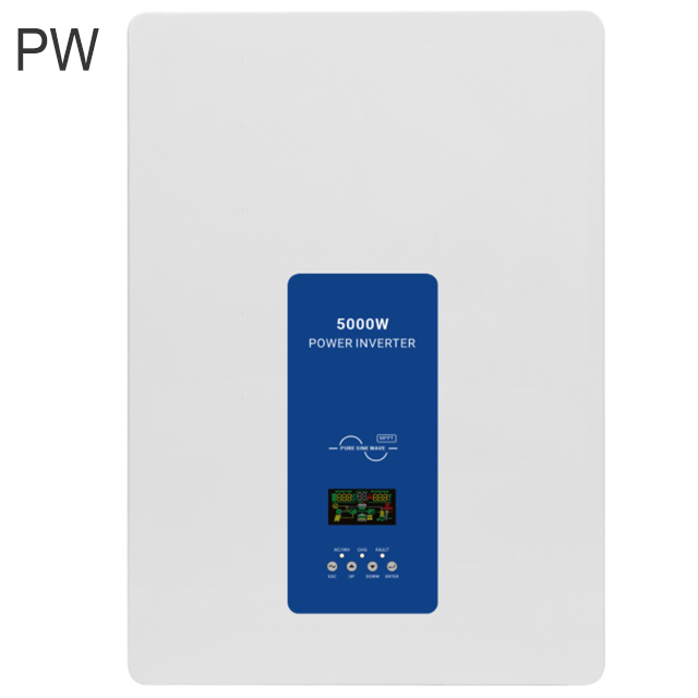
| Brand | Wone |
| Model NO. | PC/PW PV inverter |
| Mounting type | Wall-mounted |
| Rated Output Rating | 8kW |
| Input Voltage | DC48V |
| Rated PV input power | 8kW |
| Series | PC/PW series |
Photovoltaic inverter
Peculiarity:
Dual phase inverter.
IP54 protection grade, support outdoor use.
Backward compatible with traditional lead batteries, colloidal batteries.
PC/PW up to 9 parallel, output power up to 45KW.
The panel integrates a variety of interfaces, supporting a variety of protocols of the host computer and battery pack.
Integrated MPPT, maximize the press of the remaining power of the photovoltaic panel.
Highly integrated, feature-rich, one machine at most.
Can be customized adjustment management battery charging and discharging strategy.
Modular design, easy maintenance.
Technical parameter:


How does MPPT dynamically adjust the input voltage and current?