• 12kV, 17.5kV, 24kV available to 36kV Indoor Vacuum Circuit Breaker
12kV, 17.5kV, 24kV available to 36kV Indoor Vacuum Circuit Breaker
discuss personally
Model
VSC-24/1600
VSC-24/1250
VSC-24/800
VSC-24/630
VSC-12/1600
VSC-12/1250
VSC-12/800
VSC-12/630
Basic info
Brand ROCKWILL
Model NO. 12kV, 17.5kV, 24kV available to 36kV Indoor Vacuum Circuit Breaker
Rated voltage 24kV
Rated normal current 1600A
Rated frequency 50/60Hz
Series VSC
Product Detail

Product Introduction

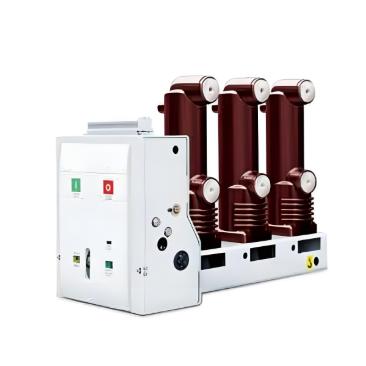
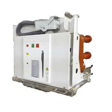
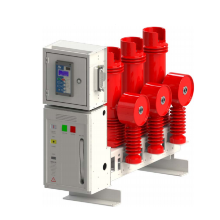
VSC medium-voltage indoor vacuum circuit breaker is applicable for three-phase AC power system of rated voltage up to 7.2kV~24kV and frequency 50/60HZ,widely used in many fields such as power plant, transformer substation, petrol chemical industry, metallurgy, manufacturing industry, airport, residential area, etc., to control and protect the electric equipment, especially, It is used for the occasion that needs infrequent operation at rated current or multi-breaking short circuit current, may be mounted in the indoor air insulating switchgear like type KYN28 or KYN96, ABB type ZS series, etc. This circuit breaker is standards as GB1984-2003 AC high voltage circuit breaker,JB3855 3.6-40.5Kv indoor AC High voltage circuit breaker,DL/T403 Specification of 12-40.5Kv indoor High voltage vacuum circuit breaker for order as well as IEC60694.

This circuit breaker is made with mature APG technology. The application of VSC terminal buffer guarantees the indoor terminal is ever more reliable in nay operation environment. VSC can fully meet the requirement of GB, DL, IEC, DIN, VDE as well as standards of other advanced industrial countries.

Service environment

  • Air temperature: Maximum temperature: +40℃; Minimum temperature:-25℃

  • Humidity: Monthly average humidity 95%; Daily average humidity 90% .

  • Altitude above sea level: Maximum installation altitude: 2500m

  • Ambient air not apparently polluted by corrosive and flammable gas, vapor etc.

  • No frequent violent shake

Main technical specifications

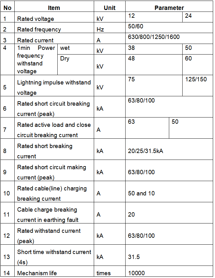
Note:For short circuit breaking current & rated current is optional by clients.

Structure & characteristic

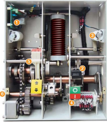
1) Wiring board for income line secondary

2) Counter

3) Closing coil

4) Auxiliary switch 8NO,8NC is optional

5) Charging chain

6) Motor

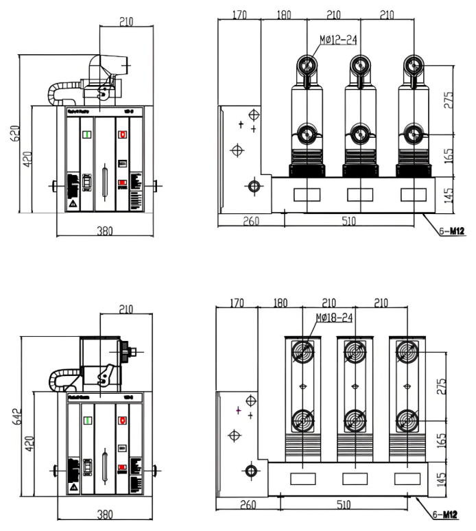
Installation sizes& outline dimensions


Know your supplier
ROCKWILL
Rockwill Electric Group Global Manufacturer of High voltage and medium-voltage power equipment and smart grid solutions. Headquartered in Wenzhou, China. Serving 100+ countries with quality, innovation, and trust. What We Offer: • HV-MV switchgear (VCB, SF₆ circuit breakers, RMU, GIS) • Distribution transformers and substations • Smart grid and monitoring systems • Solar, wind, EV charging, and energy storage solutions • EPC turnkey power projects Certified: ISO 9001 / ISO 14001 / ISO 45001
Main Categories
High voltage
Business Type
Design/Manufacture/Sales
Highest Annual Export (USD)
$150,000,000
Professional Experience
16 years
Workplace
108000m²m²
占位
占位
Documents
Public.
12kV, 17.5kV, 24kV available to 36kV Indoor Vacuum Circuit Breaker
Manual English
PDF
Related Products
Related Knowledges
Failure Analysis and Design Optimization of Conventional Grounding Transformers
I. Core Cause of Damage: Electrodynamic Impact (Complying with GB/T 1094.5 / IEC 60076-5)The direct cause of high-voltage winding end collapse is the instantaneous electrodynamic impact induced by short-circuit current. When a single-phase grounding fault occurs in the system (such as lightning overvoltage, insulation breakdown, etc.), the grounding transformer, as the fault current path, withstands high-amplitude and steep-rise-rate short-circuit currents. According to Ampère's force law
Felix Spark
06/12/2025
Analysis of Grounding Transformer Operational Behavior Under System Single-Phase-to-Ground Fault Conditions
1 Theoretical AnalysisIn distribution networks, grounding transformers serve two key roles: powering low - voltage loads and connecting arc - suppression coils at neutrals for grounding protection. Grounding faults, the most common distribution network fault, heavily impact transformers’ operating characteristics, causing sharp changes in electromagnetic parameters and status.To study transformers’ dynamic behaviors under single - phase grounding faults, build this model: Assume a tr
Felix Spark
06/12/2025
Design Calculations for Neutral Grounding Schemes and Grounding Transformer Sizing in Utility-Scale Solar PV Plants
1 Classification of Neutral Grounding Methods for Solar Photovoltaic Power StationsInfluenced by differences in voltage levels and grid structures across regions, the neutral grounding methods of power systems are mainly categorized into non-effective grounding and effective grounding. Non-effective grounding includes neutral grounding via arc suppression coils and neutral ungrounded systems, while effective grounding comprises neutral solid grounding and neutral grounding via resistors. The sel
Dyson
06/12/2025
Zero-Sequence Impedance Characterization of Dry-Type Grounding Transformer with ZN Connection
In a neutral-insulated three-phase power system, an earthing transformer provides an artificial neutral point, which can be solidly earthed or earthed via reactors/arc suppression coils. The ZNyn11 connection is typical, where zero-sequence magnetomotive forces in the inner/outer half-windings of the same core column cancel out, balancing fault currents in series windings and minimizing zero-sequence leakage flux/impedance.Zero-sequence impedance is critical: it determines fault current magnitud
Dyson
06/12/2025
Case Analysis on Maloperation of Grounding Transformer Overcurrent Protection Relay
The neutral grounding mode refers to the connection between the power system neutral point and ground. In China's 35 kV and below systems, common methods include ungrounded neutral, arc-suppression coil grounding, and small-resistance grounding. The ungrounded mode is widely used as it allows short-term operation during single-phase grounding faults, while small-resistance grounding has become mainstream for its fast fault removal and overvoltage limitation. Many substations install grounding tr
Felix Spark
06/12/2025
Discussion on the Design of Low Zero-Sequence Impedance Grounding Transformers
With the expansion of power system scale and the cableization process of urban power grids, the capacitive current in 6kV/10kV/35kV power grids has significantly increased (generally exceeding 10A). As power grids at this voltage level mostly adopt neutral ungrounded operation mode, and the distribution voltage side of main transformers is usually in delta connection, lacking a natural grounding point, the arc during ground faults cannot be reliably extinguished, necessitating the introduction o
Dyson
06/11/2025
×
Inquiry
Download
Experts Electrical is dedicated to serving the personnel in the global power industry.
Join Experts Electrical, not only can you discover power equipment and power knowledge, but also canhnd like - minded friends!
商品视频播放