252kV 363kV 550kV 800kV HV SF6 Circuit Breaker
discuss personally
Model
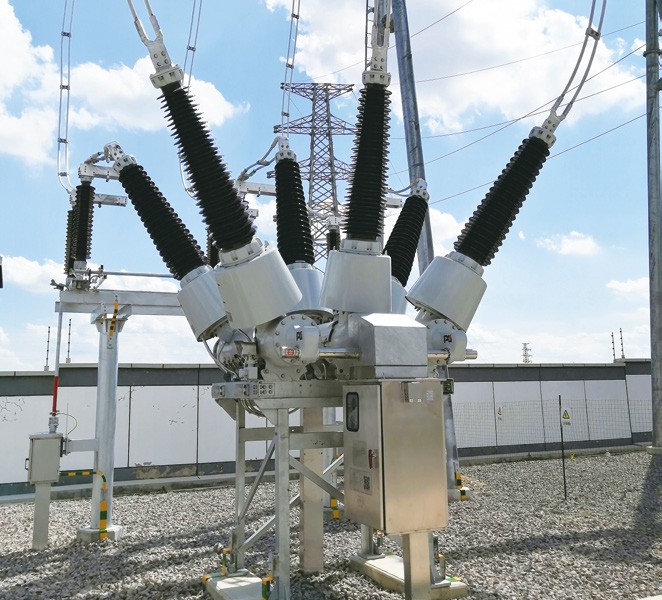
| Brand | Wone |
| Model NO. | 252KV 363KV 550KV 800KV SF6 Circuit Breaker |
| Rated voltage | 363kV |
| Rated normal current | 4000A |
| Series | LW55 |
Description:
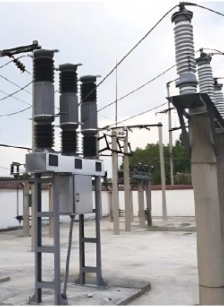
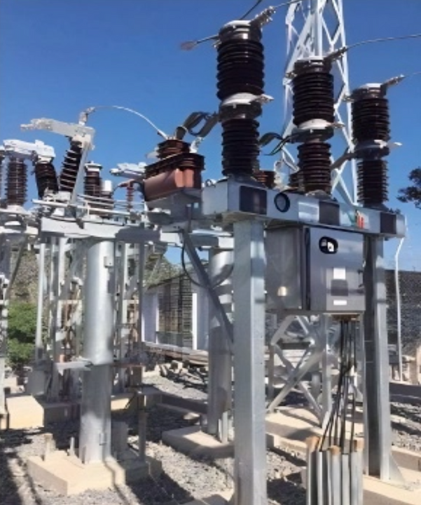
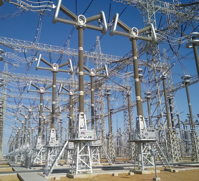
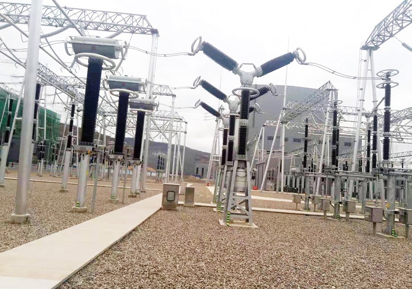
LW55 Series of SF6 Dead Tank Circuit Breaker, including LW55-252, LW55-363, LW55-550 and LW55-800, are used for making and breaking normal current, fault current and switching lines to realize the control, measurement and protection of power system.
With the advantages of excellent breaking performance, reliable mechanical properties, advanced tightness technology, high design parameters, the whole structure of circuit breaker is compact, with stable and reliable performance and long endurance.
Main Features:
The circuit breaker is of strong breaking capacity, long electrical endurance.
LW55 Series have excellent antiseismic and antipollution capacities, which make it suitable for those polluted places and higher elevation areas.
The oil pressure in hydraulic mechanism is automatic controlled and it can’t be affected by the temperature.
There are almost no external pipe for this new type of hydraulic operating mechanism, the possibility of oil leakage is reduced.
Technical Parameters:

The leakage rate of SF₆ gas must be controlled at an extremely low level, typically not exceeding 1% per year. SF₆ gas is a potent greenhouse gas, with a greenhouse effect 23,900 times that of carbon dioxide. If a leak occurs, it can not only cause environmental pollution but also lead to a decrease in the gas pressure within the arc quenching chamber, affecting the performance and reliability of the circuit breaker.
To monitor the leakage of SF₆ gas, gas leakage detection devices are typically installed on tank-type circuit breakers. These devices help to promptly identify any leaks so that appropriate measures can be taken to address the issue.