| Brand | ROCKWILL |
| Model NO. | 1250 kVA Compact substation |
| Rated voltage | 35kV |
| Capacity | 250kVA |
| Series | Compact Substation |
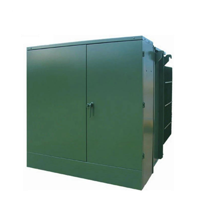
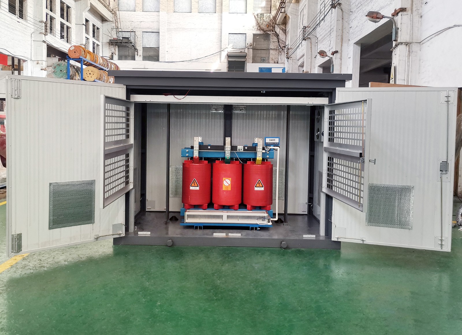
Product overview:
250- 2500kVA Compact substation can replace the traditional indoor substation, can meet the user's electric energy measurement, reactive power compensation, high and low voltage.
schemes and other configuration requirements, representing the development direction of small and medium-sized substations.
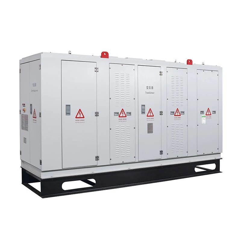
Rated AC frequency 50Hz/60HZ, maximum operating voltage to 35KV, maximum operating current to 5000A.
This product is suitable for industrial and mining enterprises, wharfs, public places, high-rise buildings and residential areas.
Products are mainly exported to Asia, Africa and other regions, providing OEM/ODM services.
Standard: IEC60067 GB 17467-2010, etc.
Product advantages:
Leading technology:
Fully enclosed and insulated structure, safe and reliable operation.
Easy to operate, maintenance-free, low equipment cost.
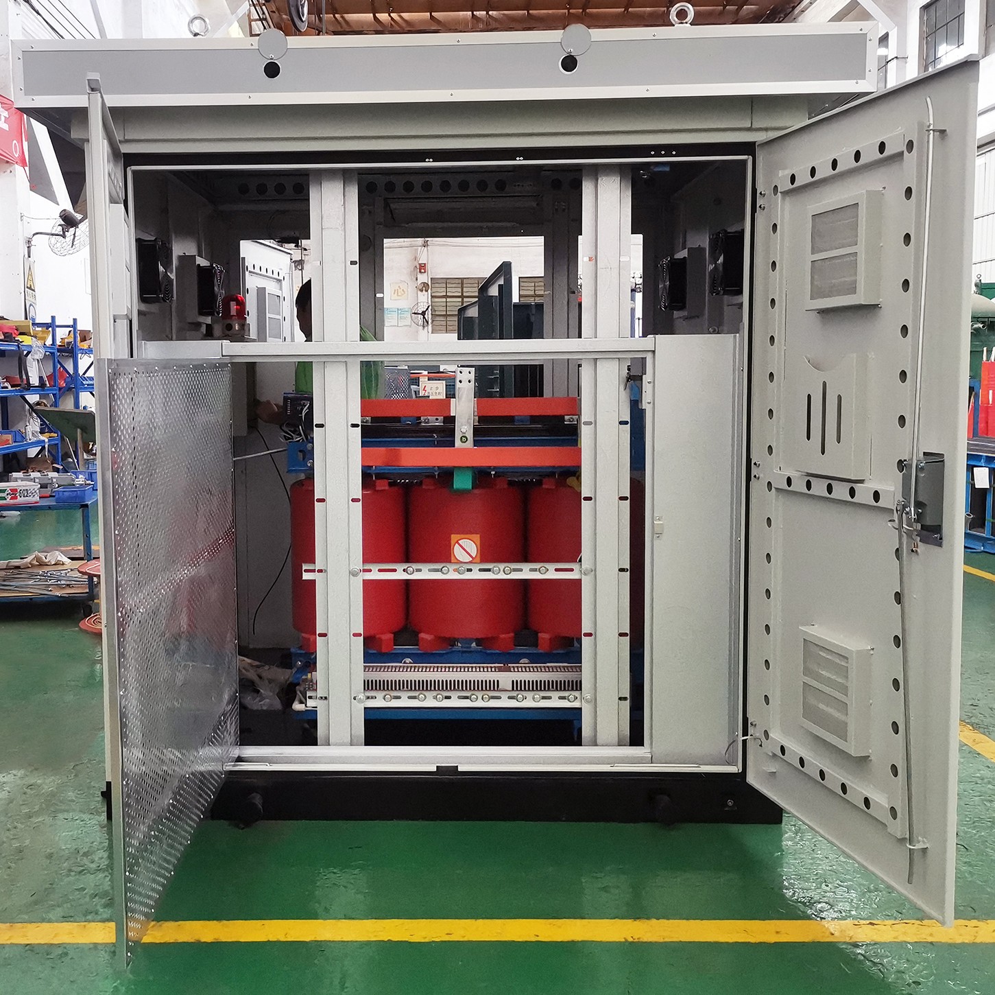
The shell:
The casing has the characteristics of firm, heat insulation and ventilation, stable performance (anti-corrosion, dustproof, waterproof) and beautiful appearance.
Various choice of shell materials, such as steel plate, composite plate, stainless steel plate, cement plate and other protection grade (IP67) .
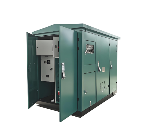
Functional units:
Divided into high voltage room, low voltage room, transformer room three independent areas.
XGN15, HXGN17 or SF6 switchgear is selected for high pressure chamber.
The low-voltage side adopts panel or cabinet mounted structure to form the power supply scheme required by users, which can meet the power distribution, lighting distribution,
reactive power compensation, energy metering and other functions. The main switch generally uses universal circuit breaker, but also can choose intelligent circuit breaker, flexible installation, easy operation.
The transformer can be fully sealed oil-immersed transformer or dry transformer.
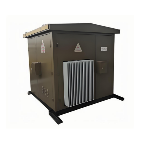
Busbar system:
Three-phase four-wire system or three-phase five-wire system.
High quality three phase tinned bus copper bar, high mechanical strength, good heat dissipation..
Product parameters:
Conditions of use:
The ambient air temperature shall not exceed a maximum of 45 ° C and a minimum of -45 ° C.
The altitude is not more than 1000m, and can reach 4000m if special custom transformers and low-voltage components are used.
The vertical inclination is not more than 5°, and there is no violent vibration and no impact.
Air humidity not greater than 90% (+25℃).
No conductive dust, no explosion hazard, no corrosive metal and electrical components in the gas place.
Outdoor wind speed should not exceed 35m/s.
The above normal operating environment conditions, customers can be customized with WONE you Electric to solve.
Ordering instructions:
The customer shall provide the following information:
Main loop scheme diagram and secondary loop system diagram.
Electrical schematic diagram of auxiliary circuit and wiring terminal layout.
Equipment layout drawing, combination drawing, floor plan drawing.
Model, specification and quantity of main electrical components of the equipment.
Incoming and outgoing line method and cable specifications.
Equipment shell material and color.
Other special requirements can be negotiated with the manufacturer.
Welcome customers to visit the factory, provide OEM/ODM protection level.