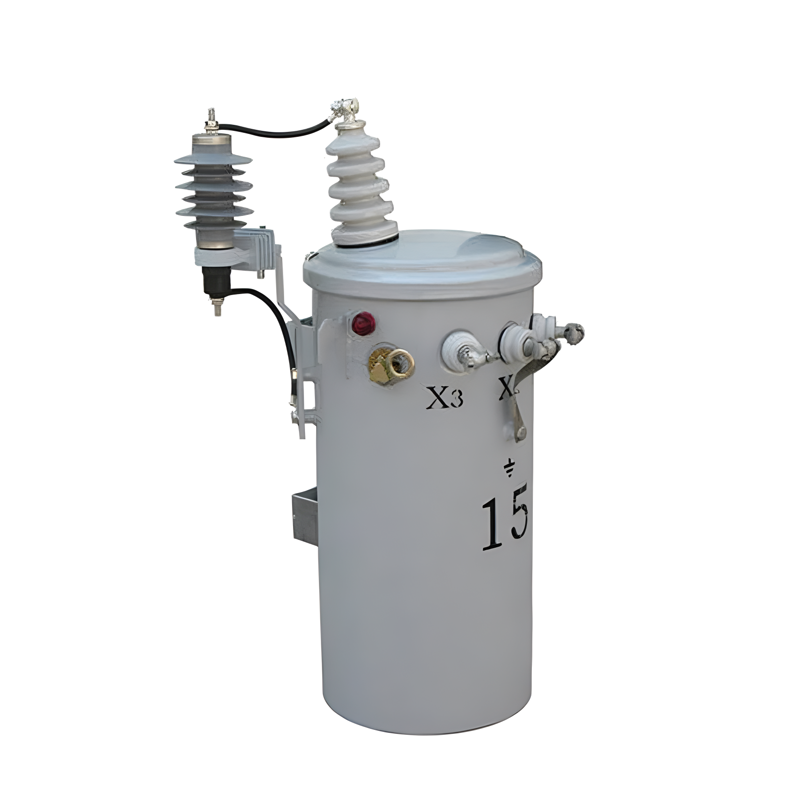
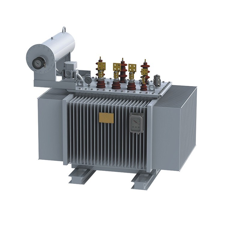
1000kVA 11kV 3 Phase Oil-immersed distribution transformer three-phase
discuss personally
Model
| Brand | Vziman |
| Model NO. | 1000KVA 11KV 3 Phase Oil-immersed distribution transformer three-phase |
| Rated voltage | 11KV |
| Rated capacity | 1000kVA |
| Series | S |
Description:
Oil immersed transformer ,use our company special calculation and validation procedures to make sure theperformance of products. superior process equipment ,elaborate materialselecting and efficient manufacturing make the transformer have smallvolume,light weight,low loss,low partial discharge,low noise characteristics.
The product is stable,reliable,economic, environmental protection.lt can beapplied to many places such as power plants,transformer substation ,largeindustrial mining and petrochemical enterprise and so on.
Features:
Ultralow no-load loss.
Energy saving and great power consuming efficiency.
Copper coil winding, strong short circuit resistance ability.
Dyn11 coil connection decrease the influences of harmonic wave.
Fully sealed structure for maintenance free.
Slow insulation aging & longer serving life.
Parameters:
Oil-immersed distribution transformer three-phase |
|
Model NO. |
S-1000-11 |
Product classification |
Distribution transformer |
Rated capacity |
1000kVA |
Primary voltage |
11kV |
Secondary voltage |
0.4kV |
Number of phase |
3 |
Number of winding |
2 |
Rated frequency |
50Hz |
Tap changer |
OCTC |
Tap range |
±2×2.5% |
Vector group |
Dyn11 |
Cooling system |
ONAN |
No-load loss |
1950+10% |
Load loss |
9500+10% |
Standard |
IEC60076 |
Impedance |
4% |
Basic insulation level |
75/28KV |
Winding material ( H.V & L.V) |
Copper |
The way the bushing appears |
Porcelain |
Power frequency withstand voltage |
—— |
Lightning impulse |
—— |
The temperature rise—Winding |
55k |
The temperature rise --Top oil |
65k |
Tank color |
—— |
Creepage distance |
—— |
Environmental requirement |
—— |
Transformer structure |
—— |
External dimensions:

Size |
1980mm×1520mm×1885mm |
Weight |
1585KG |
Environmental requirement:
Max. ambient temperature |
|
Altitude |
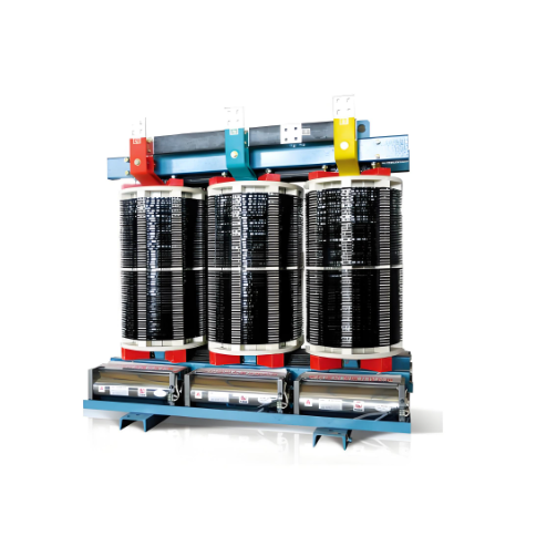
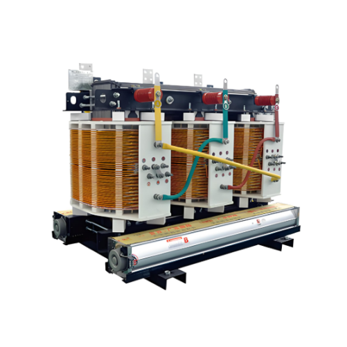
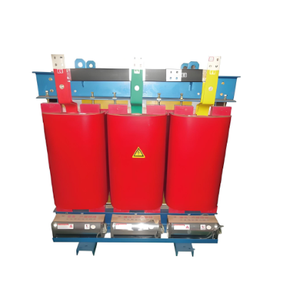
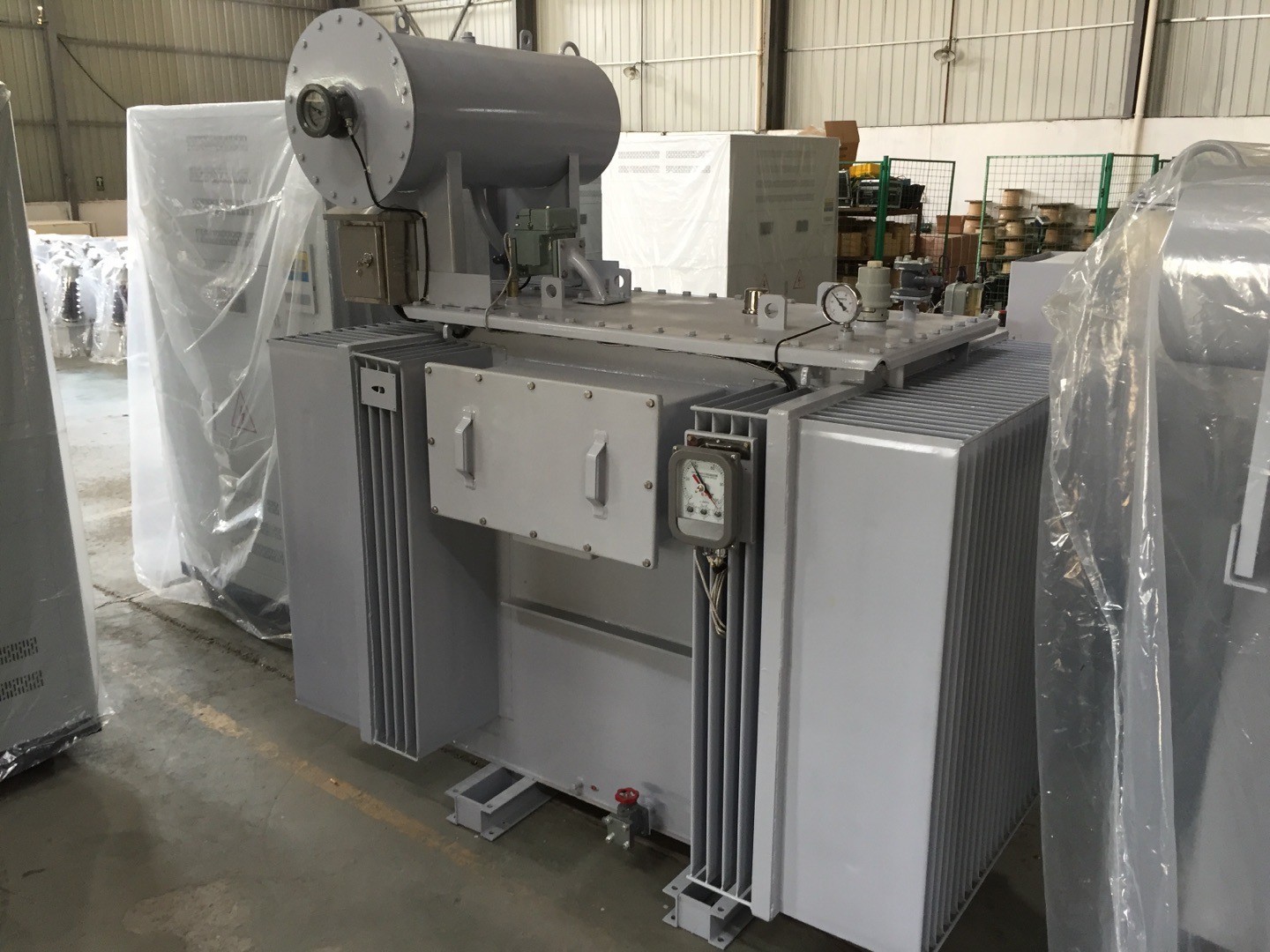
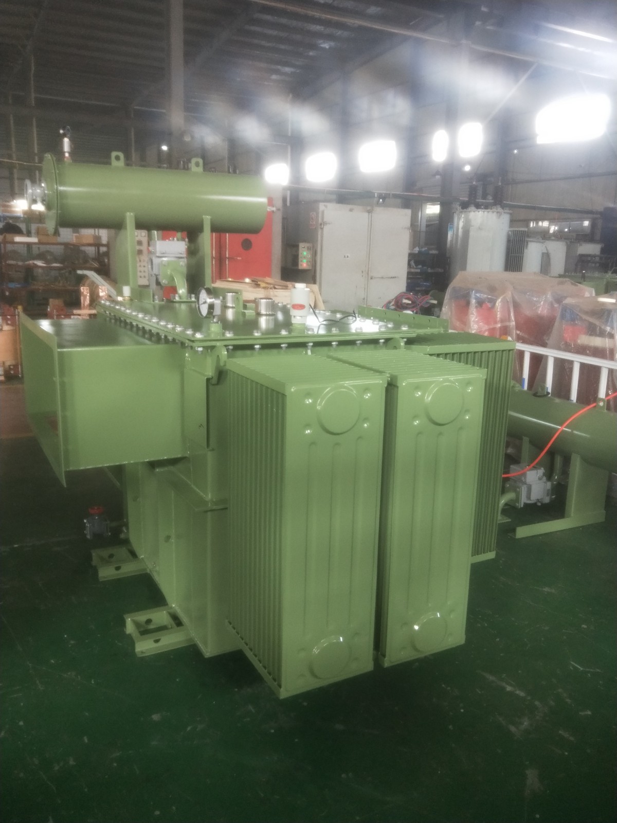
Product show:

What is no-load loss?
No - load loss, also known as iron loss or no - load iron loss, refers to the electrical energy consumed by a transformer in a no - load state (that is, the secondary winding is open - circuited and there is no load current). This part of the loss mainly occurs in the iron core of the transformer and is an inevitable part of energy loss during the operation of the transformer. Understanding no - load loss is of great significance for evaluating the efficiency of a transformer and selecting an appropriate one. The following is a detailed explanation of no - load loss:
No - load loss refers to the loss generated in the iron core when the transformer is in a no - load state, that is, when the secondary winding is open - circuited, and the primary winding is still connected to the power supply. These losses mainly consist of the following two parts:
Hysteresis loss: The loss caused by the hysteresis effect of the iron core material.
Eddy - current loss: The loss caused by eddy currents in the iron core.