What are the design and application aspects of the 10KV feeder automatic voltage regulator?

Dyson
06/19/2025

After the rural power grid renovation project, the rural distribution network has seen considerable improvement. However, due to constraints like terrain, landscape, and investment scale, the layout is not optimal. As a result, the power supply radius of some 10 kV transmission lines exceeds the reasonable range. With the changes of seasons and day and night, there are significant voltage fluctuations, leading to issues such as sub - standard power quality and relatively high line losses, which seriously affect farmers' lives and production. Thus, this paper designs a new - type voltage regulation device: the feeder automatic voltage regulator.
1 Working Principle of the Voltage Regulator
An automatic voltage regulator is a device that automatically tracks changes in the input voltage to ensure a stable output voltage. It can be widely used in 6 kV, 10 kV, and 35 kV power supply systems, and can automatically adjust the input voltage within a 20% range. Installing the device at 1/2 or 2/3 of the distance from the start of the line can ensure the voltage quality of the line.
For substations where the main transformer does not have on - load voltage regulation capability, the automatic voltage regulator can also be installed on the outgoing line side of the substation's main transformer to achieve on - load voltage regulation. There are several taps on the secondary side of the transformer. By using a single - chip microcomputer to control the on - off of thyristors, different levels of voltage regulation are provided, thus achieving the purpose of feeder voltage regulation.
2 Setting of the Voltage Regulator's Tap - changing Action Voltage
The feeder voltage regulator can adjust taps according to different load conditions and change the transformation ratio based on the line voltage to achieve voltage regulation. It has 7 taps and a 30% voltage regulation range, enabling it to well meet the rural voltage regulation requirements.
2.1 Principle of Setting the Voltage Regulator's Tap - changing Voltage
Due to load fluctuations, the voltage at the end of the line will change. For different voltage drops, it is necessary to adjust the tap settings of the voltage regulator. Figure 1 depicts a typical rural transmission power grid. Here, the line length is set as L km, and the power at the end of the line is set as S = P + jQ MVA.
 
Requirements for gear shifting: Ensure that the voltage at the end of the line varies within a 7% range; generally, gear skipping is not allowed; the number of gear shifts should be as few as possible.
Assume the transformation ratio is K, the voltage at the beginning of the line is U0, the voltage at the end of the line is U1, the input voltage of the voltage regulator is Uin, and the output voltage is Uout, with Uout=KUin.
According to the model, the following equation holds:U1=UoutΔU1.
Where Δ U1 is the voltage drop from the installation point of the voltage regulator to the end of the line, and x is the distance from the installation point of the voltage regulator to the beginning of the line. It follows that:​
(U0 - Uin) is the voltage drop from the beginning of the line to the installation point.α = U0/Uout is the line voltage level ratio before and after the installation point of the voltage regulator. Let (Lx)/x=K1, and substituting it in, we get:​
Among them, the voltage U1at the end of the line needs to satisfy the constraint condition 9.7 < U1 < 10.7. Substituting it into the above formula, the range of Uin under the condition that K is known can be obtained. However, obviously, due to the existence of U0/Uout, it is necessary to solve a quadratic equation of one variable, and there will be the problem of spurious roots. The paper simplifies this equation.
For the analysis of α=U0/ Uout, Uout and U1 have the same increasing or decreasing trend. U0 is a constant, so α=U0/ Uout, Uout is inversely proportional to U1. It can also be analyzed that when U1 = 9.3, α1; and when U1​=10.7,α is slightly less than 1. Therefore, the constraint equation can be written as:
That is:
2.2 Setting Example
As can be seen from Formula (5), in fact, the setting of the gear - shifting action only relates to the input voltage Uin of the voltage regulator and the ratio Kt of the distance from the voltage regulator installation point to the line length. There is no need to measure the actual load at the end of the line, which greatly simplifies the difficulty of actual engineering.
Take a certain actual transmission line as an example. Still use the model shown in Figure 1. The length of the transmission line is 20 km. The voltage regulator is usually installed in the middle of the line. Here, the distance from the start of the line is taken as x = 9, km, and Kt = 11/9. Substitute into Formula (5), and we can get:
For a certain gear position, the input voltage range that satisfies the quality requirements of the electric energy at the end has upper and lower limits, which are the operating voltages (shift voltages) for that gear. Each gear has its corresponding operating voltage, and this relationship can be more intuitively seen on the number axis.
Among them, Gear 1 is left unused because under normal conditions, the input voltage will not exceed the upper limit of this gear. Gear 1 can be used as a special operating condition, such as fault-tolerant operation during a single-phase ground short circuit. The following describes the switching conditions when the gear reaches the action voltage:
It should be noted that when down - shifting from gear 4, it directly shifts down to gear 2. This is because the lower action limits of gear 3 and gear 4 are relatively close. If the voltage changes greatly, after shifting down from gear 4 to gear 3, it may be necessary to immediately shift down to gear 2, which increases the number of actions. Therefore, to reduce the number of actions, cross - gear shifting is allowed.
3 Design of the Gear - shifting Controller
Currently, the commonly adopted gear - shifting method is to use a motor to drive the movement of the gear switch blade. However, how to ensure the rapid and accurate rotation of the motor has always been a problem. To achieve a better control effect, this paper adopts a thyristor control system.
3.1 Thyristor Control Principle
Thyristors can be used to realize the control of high - power circuits with weak currents. The feeder voltage regulator uses 7 pairs of bidirectional thyristors to control the gears, as shown in Figure 2. Each pair of thyristors is connected to different windings of the transformer, thus corresponding to different transformation ratios.
3.2 Design of Single - chip Microcomputer Gear - shifting Controller
The control of bidirectional thyristors only requires voltage driving from TTL gate circuits and can be directly connected to the output port of the single - chip microcomputer. To save output ports, only 3 ports are used, and an external 3 - to - 8 decoder is connected to drive the control of 7 gear positions, as shown in Figure 3.
4 Design of the Intelligent Control System
For a voltage regulator with a control chip, having only the automatic voltage regulation function is insufficient, and it also fails to fully utilize the performance of the single - chip microcomputer. A complete control system, as shown in Figure 4, also includes keyboard input, a display circuit, wireless communication, an external clock, external storage, and fault protection.
Keyboard input enables program adjustment, wireless communication allows real - time monitoring of the voltage regulator’s operation. The external clock ensures time recording during single - chip microcomputer power failure. External storage safely stores massive system operation data for future research. Fault protection makes the single - chip microcomputer enter a special operation mode under abnormal conditions to meet power transmission tasks, protects it from damage under faults, and cooperates with relay protection devices to safeguard transmission lines.
5 Conclusion
By building a transmission line model and conducting load flow calculations, the setting rules for the voltage regulator gear action voltage are determined. For transformer tap control, traditional mechanical control is replaced with more convenient and faster thyristor control, featuring simple design and good control effect. The feeder automatic voltage regulator has a wide voltage regulation range, effectively ensuring the voltage quality of transmission lines.
Dyson

Focused on the design of electrical equipment, proficient in electrical principles and relevant specifications, and skilled in using design software. From intelligent substations to various types of electrical equipment, I am adept at optimizing design solutions, integrating new technologies. With practical experience and collaborative management capabilities, I deliver outstanding electrical design achievements.

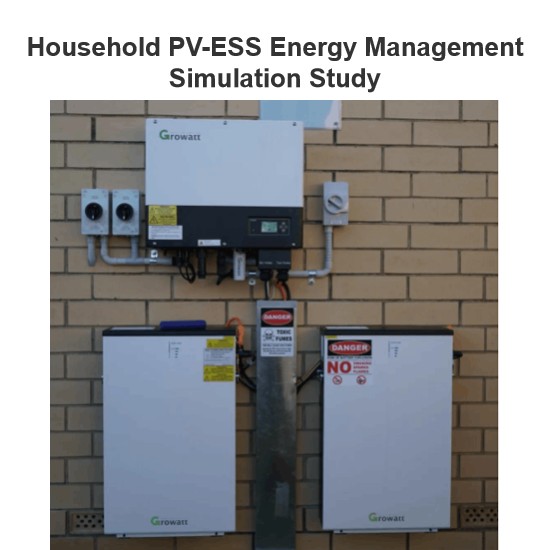
Household PV-ESS Energy Management Simulation Study
As the global energy crisis worsens and environmental pollution grows more severe, governments worldwide are boosting support for R&D in new energy power generation. The household use of solar distributed generation, a key next - phase direction for the PV industry, has gained increasing attention. However, issues like power output fluctuations of PV components and the rationality of energy storage unit integration can seriously affect household electricity use. Thus, to coordinate stable en
Dyson
06/26/2025
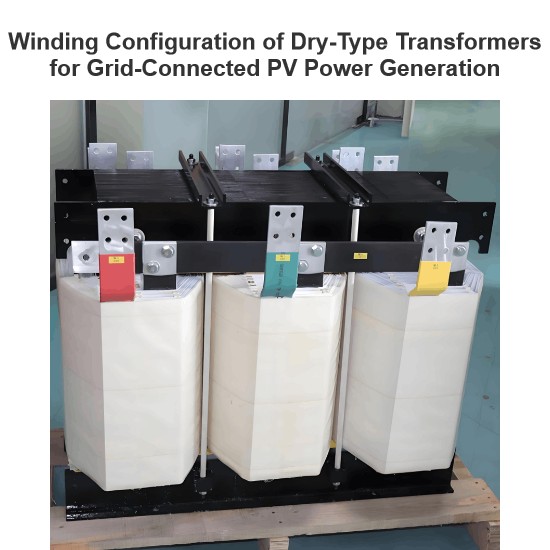
Winding Configuration of Dry-Type Transformers for Grid-Connected PV Power Generation
Solar photovoltaic power generation, a key form of solar energy use, converts sunlight to electricity via solar cells. Free from resource, material, or environmental limits and eco - friendly, it has broad prospects and is a priority renewable energy tech globally. In grid - connected PV systems, transformers (core energy - conversion gear) are essential. Current step - up transformers for PV mainly use 10 kV/35 kV SC - series epoxy - insulated dry - type units, split into two - winding and doub
Dyson
06/25/2025
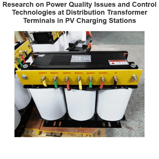
Research on Power Quality Issues and Control Technologies at Distribution Transformer Terminals in PV Charging Stations
1. IntroductionAs a frontline designer of photovoltaic charging station distribution systems, I deeply engage in power quality control technology research. Amid energy transition, photovoltaic charging stations grow in importance, yet large - scale PV integration brings power quality challenges. The distribution transformer end, a key node, urgently needs solutions. Despite existing research, gaps remain in control tech considering PV characteristics and complex conditions. This paper focuses on
Dyson
06/24/2025
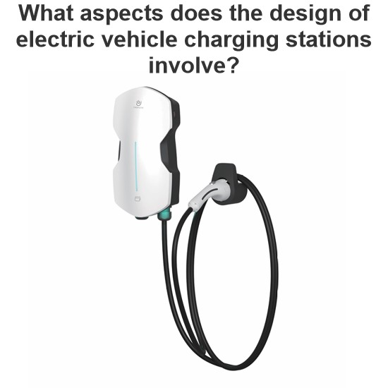
What aspects does the design of electric vehicle charging stations involve?
As a frontline designer, I work on EV charging piles daily. Amid worsening global climate change and China’s rapid economic growth, green mobility like e - bikes and electric cars has boomed, yet charging issues have become a focal concern. The risky “Bypass Wire” charging has spurred huge demand for professional piles. Having taken part in the CNPC First Construction residential charging pile renovation, I’m sharing my hands - on experience.I. Industry Context(1) Electri
Dyson
06/23/2025
Inquiry
Download
Experts Electrical is dedicated to serving the personnel in the global power industry.
Join Experts Electrical, not only can you discover power equipment and power knowledge, but also canhnd like - minded friends!