Dual Fuzzy-Sugeno Method to Enhance Power Quality Performance Using a Single-Phase Dual UPQC-Dual PV Without DC-Link Capacitor
This paper proposes a novel configuration of a dual UPQC supplied by a dual photovoltaic (PV), hereinafter referred to as 2UPQC-2PV, to improve the power quality performance of a single-phase 220 V/50 Hz distribution system. The 2UPQC-2PV configuration is proposed to anticipate the possible failure of both inverters in one of the UPQC circuits. The PV array replaces the DC-link capacitor to maintain its voltage connected to the DC-link of the UPQC constant while at the same time supplying active power to the load during an interruption voltage. The dual-fuzzy Sugeno (dual-FS) method is used to overcome the weakness of the dual-proportional-integral (dual-PI) control in determining the optimum parameters of proportional and integral constants.
1.Introduction
Many papers have discussed the deployment of dual UPQC circuits and control to enhance the power quality of supply and load of the low-voltage distribution network.The sinusoidal reference synchronization theory was used to build a straightforward UPQC control approach in the ABC reference frame in, whereas in, two distinct controls were compared to produce a pulse width modulation (PWM) reference signal using the α−β and d-q reference frames, respectively. There have already been simulations, and lab tests comparing the operating performance of single UPQC and dual UPQC in a three-phase three-wire (3P3W) system under static and dynamic faults as well as providing additional adjustment to the grid voltage. Dual UPQC was able to produce better static and dynamic performance than single UPQC, according to the simulation and experimental data.
2. Research Method
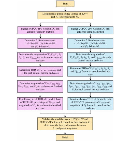
In this study, the single-phase Se-AF circuit consists of four MOSFET switches (MO1, MO2, MO3 and MO4) which inject a compensating voltage to the load bus when a sag/swell occurs on the source bus. The single-phase Sh-AF circuit consists of four IGBT switches (IG1, IG2, IG3 and IG4) that inject harmonic compensation current to the source bus because of the presence of nonlinear load (NL). In the proposed model, the NL is a full-bridge rectifier with diodes (D1, D2, D3 and D4) connected to a RL DC load.
The two proposed power electronics devices are the 1UPQC-1PV array and the 2UPQC-2PV arrays. To overcome the shortcomings of the 1UPQC-1PV system and maintain the magnitude of the load voltage while simultaneously reducing the load voltage THD and providing the load bus with a more stable active power supply in the event of voltage interruption on the source bus, the 2UPQC-2PV system is proposed. The suggested UPQC circuit does not include a DC-link capacitor, in contrast to other studies.
3. Result and Discussion
By using Matlab Simulink, each model combination is executed according to the proposed case to obtain the waveforms of the source voltage (VS), series voltage (VSE), load voltage (VL), source current (IS), shunt current (ISH), and load current (IL). Based on the waveforms, their magnitudes and corresponding THDs are obtained. The measurement of the magnitude of the voltage, nominal current, and THD values in each UPQC-PV combination was carried out in 3 cycles between 0.22 s-0.28 s. The next process performs simulations on a number of proposed cases to obtain curves and determine the values of PV voltage (VPV), PV current (IPV), and PV power (PPV), and their contribution to changes in load active power (PL), which are carried out in one cycle at 0.25 s. The PV power value is measured after the DC-DC boost converter circuit so its value is the same as the DC-link power because the UPQC circuit does not use capacitors.
4.Conclusion
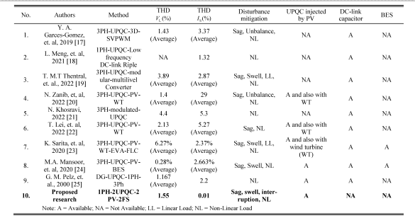
The 2UPQC-2PV configuration to improve power quality performance in a single-phase 220 V / 50 Hzdistribution system has been implemented together with the 1UPQC-1PV configuration. The 2UPQC-2PV configuration is proposed to anticipate the failure of the two inverters in one of the UPQC circuits. The proposed model does not use a DC-link capacitor whose role is replaced by a PV generator to keep the UPQC DC voltage constant, while at the same time supplying power to the load during interruptions. The dual-FS method is used to overcome the weakness of the dual-PI control in determining the optimum parameters of proportional and integral constants. Disturbance simulations are carried out for the 2UPQC-2PV and 1UPQC-1PV configurations using dual-FS and dual-PI controls, and three cases, i.e., Case 1 (S-Sag-NL), Case 2 (S-Swell-NL), Case 3 (S-Inter-NL).
Source: IEEE Xplore
Statement: Respect the original, good articles worth sharing, if there is infringement please contact delete.
IEEE (pronounced "I-triple-E") stands for the Institute of Electrical and Electronics Engineers, a global professional organization dedicated to advancing technological innovation for the benefit of humanity. Founded in 1963 through the merger of the American Institute of Electrical Engineers (AIEE) and the Institute of Radio Engineers (IRE), IEEE has grown into the world’s largest technical professional society, with over 400,000 members across 160+ countries.
