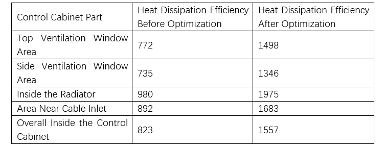
Thermal Optimization Design for Control Cabinets of Pad-Mounted Transformers in Offshore Wind Turbines
Dyson
06/17/2025
Focused on the design of electrical equipment, proficient in electrical principles and relevant specifications, and skilled in using design software. From intelligent substations to various types of electrical equipment, I am adept at optimizing design solutions, integrating new technologies. With practical experience and collaborative management capabilities, I deliver outstanding electrical design achievements.
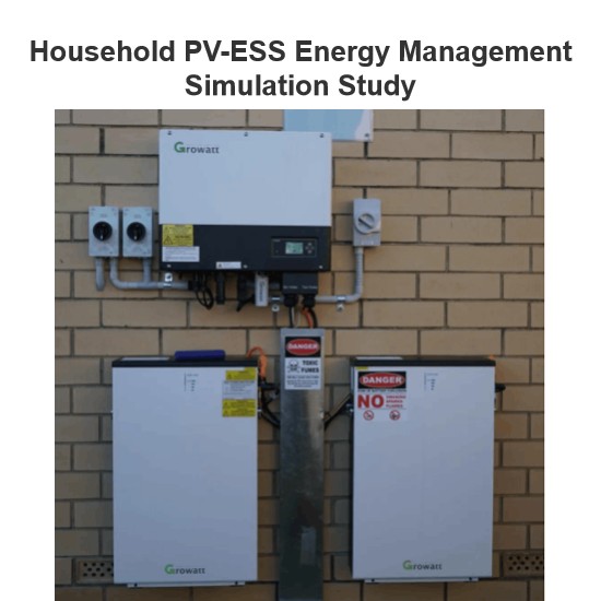
Household PV-ESS Energy Management Simulation Study
As the global energy crisis worsens and environmental pollution grows more severe, governments worldwide are boosting support for R&D in new energy power generation. The household use of solar distributed generation, a key next - phase direction for the PV industry, has gained increasing attention. However, issues like power output fluctuations of PV components and the rationality of energy storage unit integration can seriously affect household electricity use. Thus, to coordinate stable en
Dyson
06/26/2025
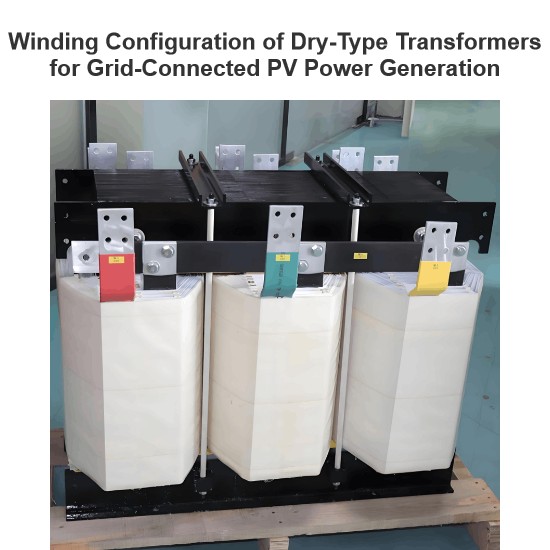
Winding Configuration of Dry-Type Transformers for Grid-Connected PV Power Generation
Solar photovoltaic power generation, a key form of solar energy use, converts sunlight to electricity via solar cells. Free from resource, material, or environmental limits and eco - friendly, it has broad prospects and is a priority renewable energy tech globally. In grid - connected PV systems, transformers (core energy - conversion gear) are essential. Current step - up transformers for PV mainly use 10 kV/35 kV SC - series epoxy - insulated dry - type units, split into two - winding and doub
Dyson
06/25/2025
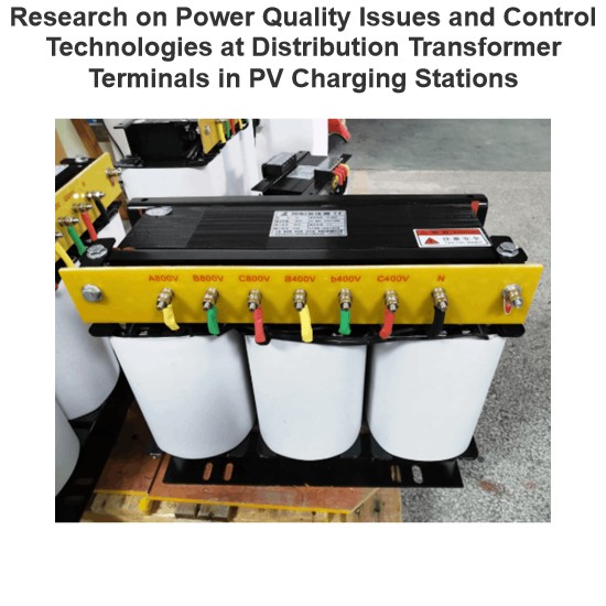
Research on Power Quality Issues and Control Technologies at Distribution Transformer Terminals in PV Charging Stations
1. IntroductionAs a frontline designer of photovoltaic charging station distribution systems, I deeply engage in power quality control technology research. Amid energy transition, photovoltaic charging stations grow in importance, yet large - scale PV integration brings power quality challenges. The distribution transformer end, a key node, urgently needs solutions. Despite existing research, gaps remain in control tech considering PV characteristics and complex conditions. This paper focuses on
Dyson
06/24/2025
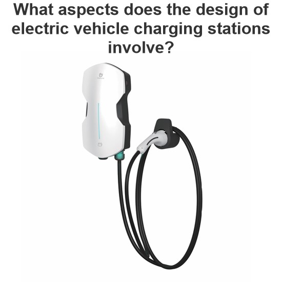
What aspects does the design of electric vehicle charging stations involve?
As a frontline designer, I work on EV charging piles daily. Amid worsening global climate change and China’s rapid economic growth, green mobility like e - bikes and electric cars has boomed, yet charging issues have become a focal concern. The risky “Bypass Wire” charging has spurred huge demand for professional piles. Having taken part in the CNPC First Construction residential charging pile renovation, I’m sharing my hands - on experience.I. Industry Context(1) Electri
Dyson
06/23/2025
