Prototype Development of 20 kV Single-Phase Distribution Transformer

Dyson
06/17/2025

1. Design of 20 kV Single - phase Distribution Transformer
20 kV distribution systems usually adopt cable lines or mixed cable - overhead line networks, and the neutral point is mostly grounded through a small resistance. When a single - phase grounding occurs, there will be no problem that the phase voltage will rise by more than √3 times as in the case of a single - phase fault in a 10 kV system. Therefore, the single - phase distribution transformer of the 20 kV system can adopt the type of grounding the end of the coil. This can reduce the main insulation of the single - phase distribution transformer, making the volume and cost of the 20 kV single - phase distribution transformer not much different from those of the 10 kV one.
2. Selection of Impulse and Test Voltages
For the basic impulse level (BIL) and insulation test level of the 20 kV single - phase distribution transformer, considerations are as follows:
The American National Standard ANSI C57.12.00—1973 (IEEE Std 462—1972) stipulates that the basic impulse level (BIL) of the high - voltage side (20 kV) is 125 kV; the rated voltage of the high - voltage component is 15.2 kV, and the AC withstand voltage (60 Hz/min) is 40 kV.
The insulation test stipulates that the applied voltage test is not required, but the induced voltage test must be carried out. During the test, after applying a voltage to the outgoing terminal of one winding, the voltage of each high - voltage outgoing terminal to the ground reaches 1 kV plus 3.46 times the rated voltage of the transformer winding. That is, in the induction test (frequency - doubled and voltage - doubled test), the high - voltage is:

2.1 Low-voltage Side (240/120 V)

  • Basic Impulse Level (BIL): 30 kV
  • AC Withstand Voltage (60 Hz/min): 10 kV

2.2 According to China’s National Transformer Quality Supervision Test Regulations

  • High-voltage side:
    • Basic Impulse Level (BIL): 125 kV (full wave), 140 kV (chopped wave)
    • AC Induced Withstand Voltage (200 Hz/min): 40 kV
  • Low-voltage side:
    • Applied Voltage (50 Hz/min): 4 kV
3. Structure and Features of 20 kV Single-phase Distribution Transformers
Two specifications (50 kVA and 80 kVA) were prototyped, both adopting an outer - iron structure. To reduce main insulation, an end - insulation structure was added. A single bushing is used for lead - out. The end of the high - voltage coil is grounded and connected to the tank. The low - voltage winding is a single - coil structure.
3.1Technical Performance Comparison Between Prototyped 20 kV and 10 kV Single-phase Distribution Transformers
  • Loss comparison between 20 kV and 10 kV (taking 50 kVA and 80 kVA as examples) is shown in Table 1.

  • Weight comparison between 20 kV and 10 kV (taking 50 kVA and 80 kVA as examples) is shown in Table 2.

4. 20 kV∥10 kV Single - phase Dual - voltage Distribution Transformer
Upgrading a 10 kV to a 20 kV distribution system involves replacing key equipment like distribution transformers. High - cost replacements and power outages disrupting production make designing a dual - voltage (10 kV/20 kV) single - phase transformer a solution to ease these issues.
4.1 Design
Based on the 10 kV wound - core single - phase distribution transformer, this dual - voltage variant leverages the 20 kV = 2×10 kV relationship, using series - parallel primary coils. With two parallel high - voltage coils, two core columns get high - voltage/low - voltage windings (high - voltage coils parallel). Two low - voltage coils series at the “mid - point” output ±220 V - ground for two users. Let W1 (high - voltage turns) and W2 (low - voltage turns). In parallel, U1/U2 = W1/W2 = 10 kV/220V, and total high - voltage current doubles a single coil’s. In series, high - voltage input current equals coil current.
4.2 Switching Application
Capacity stays consistent for 20 kV or 10 kV high - voltage inputs. At 20 kV input, two high - voltage coils in series mean each bears 10 kV. With high - voltage current I1, capacity S1 = I1×20 = 20I1(kVA). Switched to 10 kV, parallel high - voltage coils give 2I1 input current, so S1 = 2I1×10 = 20I1 (kVA). Thus, S1 = S2).
4.3 Structure
  • Structure matches the single - phase wound - core transformer (patent No. 4612429).
  • 10 kV/20 kV voltage - switching uses a reliable contact strip tap - changer.
  • Insulation meets IEC 20 kV transformer standards (rated impulse voltage: 125 kV).
  • Noise complies with IEC and relevant power company technical specs.

4.4 Advantages of Single - phase Dual - voltage Transformer

  • Energy Conservation:The line loss of the 20 kV distribution system is 25% of that of the 10 kV distribution system, achieving a 75% energy savings. By adopting the single - phase wound - core technology in this design, the no - load loss of the transformer is 30% lower than that of the currently used S11 - type distribution transformer.
  • Construction Cost Savings:During the upgrade from 10 kV to 20 kV, only a changeover switch is needed to switch the voltage. This reduces the power outage time, and the entire operation process can be completed within just a few minutes.

5. Conclusion

  • Most neutral points of the 20 kV system are grounded through a small - resistance system. Therefore, it is easier to handle the main insulation of single - phase transformers at the 20 kV level compared to the 10 kV level.
  • The load loss of 20 kV - class single - phase transformers is at the same level as that of 10 kV - class ones; their weight is also at a comparable level. In terms of no - load loss, 20 kV is lower than 10 kV. Regarding impedance, the 20 kV single - phase transformer is 20% higher than the 10 kV one.
  • The 20 kV single - phase transformer is relatively economical. Its price will not differ significantly from that of 10 kV - class single - phase transformers.
  • The 20 kV∥10 kV single - phase dual - voltage distribution transformer can be used in both 10 kV and 20 kV distribution systems. When upgrading a 10 kV system to a 20 kV system, there is no need to replace the transformer; simply switching the changeover switch suffices. It is a relatively economical and convenient method.
Dyson

Focused on the design of electrical equipment, proficient in electrical principles and relevant specifications, and skilled in using design software. From intelligent substations to various types of electrical equipment, I am adept at optimizing design solutions, integrating new technologies. With practical experience and collaborative management capabilities, I deliver outstanding electrical design achievements.
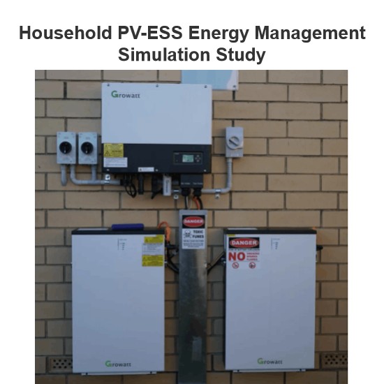
Household PV-ESS Energy Management Simulation Study
As the global energy crisis worsens and environmental pollution grows more severe, governments worldwide are boosting support for R&D in new energy power generation. The household use of solar distributed generation, a key next - phase direction for the PV industry, has gained increasing attention. However, issues like power output fluctuations of PV components and the rationality of energy storage unit integration can seriously affect household electricity use. Thus, to coordinate stable en
Dyson
06/26/2025
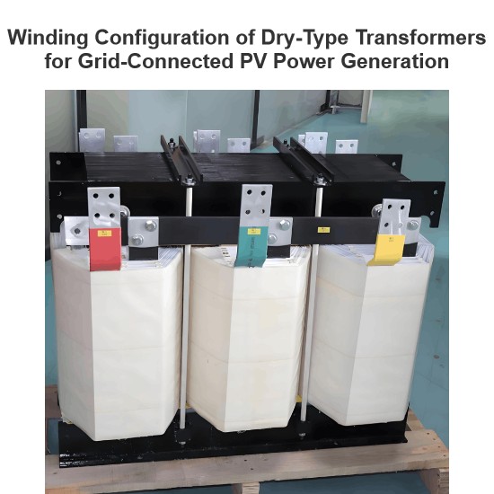
Winding Configuration of Dry-Type Transformers for Grid-Connected PV Power Generation
Solar photovoltaic power generation, a key form of solar energy use, converts sunlight to electricity via solar cells. Free from resource, material, or environmental limits and eco - friendly, it has broad prospects and is a priority renewable energy tech globally. In grid - connected PV systems, transformers (core energy - conversion gear) are essential. Current step - up transformers for PV mainly use 10 kV/35 kV SC - series epoxy - insulated dry - type units, split into two - winding and doub
Dyson
06/25/2025
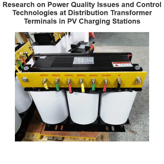
Research on Power Quality Issues and Control Technologies at Distribution Transformer Terminals in PV Charging Stations
1. IntroductionAs a frontline designer of photovoltaic charging station distribution systems, I deeply engage in power quality control technology research. Amid energy transition, photovoltaic charging stations grow in importance, yet large - scale PV integration brings power quality challenges. The distribution transformer end, a key node, urgently needs solutions. Despite existing research, gaps remain in control tech considering PV characteristics and complex conditions. This paper focuses on
Dyson
06/24/2025
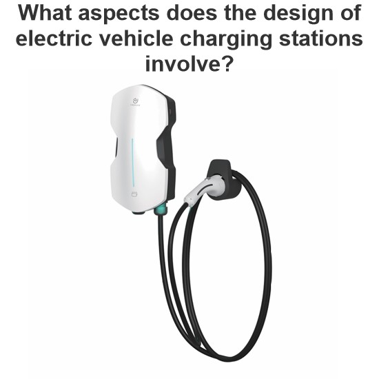
What aspects does the design of electric vehicle charging stations involve?
As a frontline designer, I work on EV charging piles daily. Amid worsening global climate change and China’s rapid economic growth, green mobility like e - bikes and electric cars has boomed, yet charging issues have become a focal concern. The risky “Bypass Wire” charging has spurred huge demand for professional piles. Having taken part in the CNPC First Construction residential charging pile renovation, I’m sharing my hands - on experience.I. Industry Context(1) Electri
Dyson
06/23/2025
Inquiry
Download
Experts Electrical is dedicated to serving the personnel in the global power industry.
Join Experts Electrical, not only can you discover power equipment and power knowledge, but also canhnd like - minded friends!