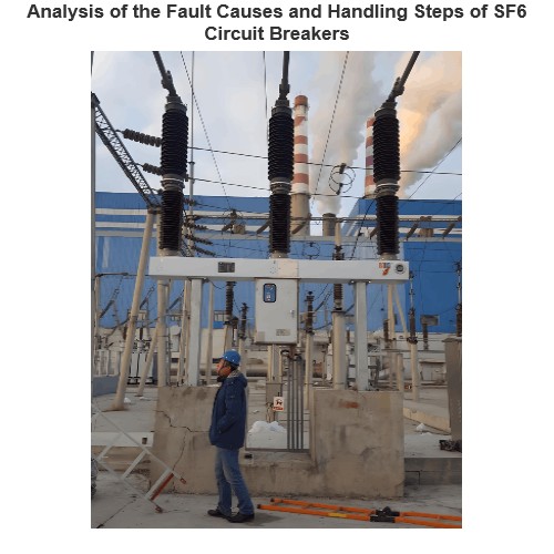
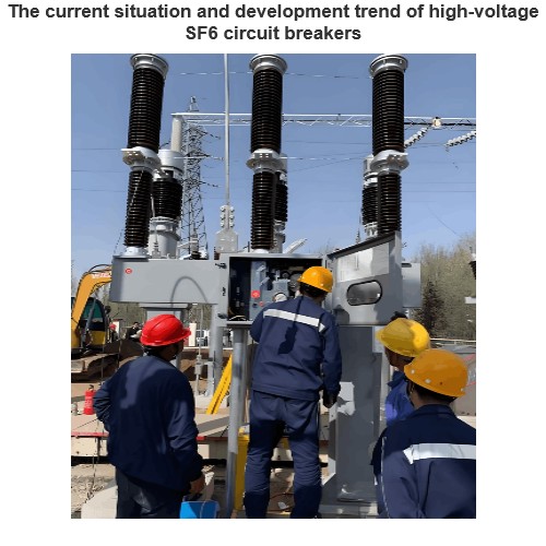
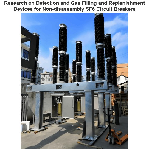
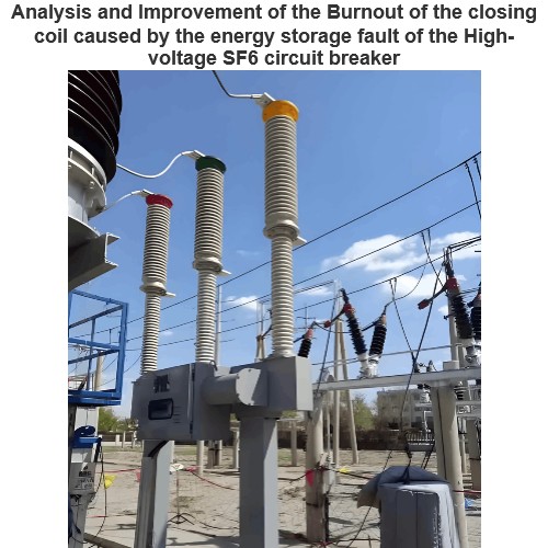
With the advancement of technology and the improvement of production levels, the performance and quality of SF₆ circuit breaker equipment have been continuously enhanced, and the products have been widely recognized by customers. However, with its extensive application, the frequency of faults has also increased. The causes of faults include issues such as design principles, manufacturing processes, and material selection. Through investigation and statistics on the causes of faults, it is known that 20%-30% of the problems are caused by the leakage of SF₆ gas. Gas leakage detection is a crucial and indispensable point during the electrical installation stage.
1 Main Causes
Leakage is a very common situation. Leakage problems occur wherever there are differences in content, temperature, and pressure. Scientific remedies should be adopted for different leakage phenomena, and the source of leakage should be found out in a timely manner.
1.1 External Leakage of Hydraulic Machines
For various hydraulic machines, the leakage positions and situations may vary. Generally, the common leakage positions are:
- Valves, seals, and gaskets. Three-way switches, oil drain switches, primary switches, secondary switches, protection valves, etc. The causes of leakage include improper closure of the valve core, uneven contact surface due to insufficient production precision; sand holes in the valve body, unsealed position, and loose gas release bolts.
- The connection positions of pressure gauges and electromechanical equipment. The sealing gaskets of these joints may be uneven or lose their elasticity, which is likely to cause leakage.
- The sealing surfaces of the operating cylinder piston and the accumulator cylinder piston provided by the manufacturer. Since the seals and gaskets at these positions are often subject to movement friction, they are prone to deformation, deterioration, or damage.
The consequences of leakage in hydraulic machines are very serious. Minor leakage not only affects the cleanliness of the equipment but also inevitably leads to repeated pressurization of the oil pump and a long pressure replenishment cycle. Massive oil leakage in the valve body will cause a pressure loss problem. When the hydraulic oil enters the accumulator cylinder, the pressure on the gas side will continuously increase, resulting in emergency repairs, misoperation, and equipment defects, which will hinder the safe operation of the equipment.
1.2 External Leakage at the Main Body and Connection
- Welds. Due to a large current during welding, the welds may be burned through, resulting in micro-leakage. After a certain period, the leakage amount will continuously increase. At the welding positions of two different materials, due to high local stress, weld cracks will also cause leakage. With the improvement of the manufacturer's manufacturing technology, the probability of this phenomenon occurring during the on-site installation and operation stages is relatively small.
- The connection position between the supporting porcelain bushing and the flange. Because of the high pressure at this position, leakage is likely to occur if the sealing is not tight, such as rough manufacturing of the porcelain bushing joint surface, uneven joint surface, and uneven or unstable bonding of the seal ring.
- Pipeline joints, density relay equipment interfaces, the ends of pressure gauges, the cover of the three-way box, and other positions. These positions are the most common areas for connections, closures, and welding, and they are the difficult and weak points of sealing, with a high probability of leakage.
For SF₆ gas, the sealing surface at any position must be kept very clean. Otherwise, even a small amount of foreign matter stuck at the sealing surface can increase the leakage rate to the order of 0.001MPa.M1/s, which is not allowed for the equipment. Therefore, before installation, the sealing surface and gasket should be carefully wiped with a white cloth and high-quality toilet paper dipped in alcohol, and a detailed inspection should be carried out. Assembly can only be carried out after confirming that there are no problems. In addition, the dust on the flange, bolt holes, and connecting bolts should be wiped off to prevent it from entering the sealing surface, especially during the installation of the vertical seal.
2 SF₆ Circuit Breaker Leakage Detection Methods
2.1 Liquid Surface Tension Method
The basic principle is that for liquids with strong surface tension such as soapy water, bubbles will appear at the leakage point when gas leaks. The detection method is to apply soapy water and other substances on the outer shell of the SF₆ circuit breaker and the possible leakage points.
Disadvantages: High requirements for smearing, unable to detect minor leaks, and some positions cannot be smeared.
Advantage: Intuitive.
2.2 Qualitative Leakage Detection
The basic principle is that SF₆ has strong electronegativity. Under the influence of pulsed high voltage, a continuous discharge effect occurs, and the SF₆ gas will change the performance of the corona electric field, thereby detecting the presence of SF₆ gas on-site. This is only to determine the relative degree of leakage of the SF₆ circuit breaker equipment, rather than detecting its actual leakage rate. Qualitative leakage detection includes the following methods:
- Vacuum pumping detection. Pump the vacuum to 133Pa, keep pumping for more than 30 minutes, stop the pump, read the value A after observing for 30 minutes, and then read the value B after observing for 5 hours. If 67Pa > B - A, it can be determined that the sealing is good.
- Foaming liquid detection. This is a relatively simple qualitative leakage method that can accurately find the leakage point. The foaming liquid can be prepared by adding a neutral soap to two parts of water. Apply the foaming liquid to the position to be detected for leakage. If bubbles appear, it indicates leakage at this position. The more and more urgent the bubbles are, the more serious the leakage is. This method can roughly find the leakage position with a leakage rate of 0.1ml/min.
- Leakage detector detection. The leakage detector detection is to move the probe of the leakage detector along the surface of each connection of the circuit breaker and the surface of the aluminum casting, and determine the leakage situation according to the reading of the leakage detector . When using this method, the following techniques should be mastered: First, the movement speed of the probe should be slow to prevent missing the leakage due to too fast movement. Second, the detection should not be carried out in a strong wind to prevent the leakage from being blown away and affecting the detection. Third, a leakage detector with high sensitivity and low response speed should be selected. Generally, the minimum detectable amount of the leakage detector is that the leakage rate is lower than 10-6, and the response speed is lower than 5s, which is more appropriate.
- Segmentation and positioning method. This method is suitable for circuit breakers with three-phase SF₆ gas circuit connections. If leakage is determined but it is difficult to locate, the SF₆ gas structure can be divided into several parts for detection, thereby reducing blindness.
- Pressure reduction method. This method is applicable when the leakage amount of the equipment is large.
2.3 Quantitative Leakage Detection
This is to detect the leakage rate of the SF₆ circuit breaker, and the judgment standard is that the annual leakage rate does not exceed 1%. The specific methods are as follows: (1) Local Wrapping Method: Use a plastic film with a thickness of 0.01 cm to wrap around the geometric shape of the density position for one and a half circles, with the joint facing upwards. Try to form a circular or square shape, and seal it with adhesive tape after shaping [3]. There should be a certain gap, approximately 0.05 cm, between the plastic film and the object being measured. After wrapping, detect the content of SF₆ gas in the wrapped cavity after 24 hours, and select the average value of four points at different positions. The leakage rate of this sealing process can be calculated using the following formula:F=ΔC⋅(V−ΔV)⋅P/Δt(MPa⋅m3/s)
Where:
- F: Absolute leakage rate, leakage amount per unit time (MPa⋅m3/s).
- Δ C: Average value of the detected leakage content (ppm).
- ΔV: Volume between the object being measured and the plastic film (m3).
- Δt: Time interval for detecting ΔC(s).
- P: Absolute atmospheric pressure, which is 0.1MPa.
- V: Volume of SF₆ gas in the gas chamber (m3).
The annual leakage rate Fy of each gas chamber is calculated as follows: Fy=F⋅31.5×10⁻⁶/V⋅(Pr+0.1)⋅100% (per year) Where Pr is the specified SF₆ gas pressure (MPa).
When starting the above calculations, the following parameters are difficult to determine:
- Δ V: Since the volume between the object being measured and the plastic film has an irregular shape, its volume cannot be directly calculated. Experimental methods can be adopted, such as injecting other gases and liquids through a flowmeter into the wrapped cavity to collect volume information.
- V and W: The gas volume and mass of SF₆ in the gas chamber. This information is not provided by the manufacturer. You can require the manufacturer to provide accurate information in the order technical documents, or use a metering method during gas filling to obtain more precise information.
Hanging Bottle Detection Method: Hang a bottle at the detection hole of the insulator. After a few hours, use a leakage detector to detect whether there is leaked SF₆ gas in the bottle.
2.4 Infrared Detection
The infrared detection method mainly uses the strong infrared absorption property of SF₆ gas. SF₆ gas has the strongest absorption of infrared rays with a wavelength of 10.6um. Common infrared detection methods include the infrared laser method and the passive detection method.
The working principle of laser infrared detection is that an incident infrared laser is transmitted by the laser transmitter, and the backscattered laser enters the laser camera imaging platform through reflection. If the incident laser encounters leaked SF₆ gas, some of its energy will be absorbed, resulting in differences in the backscattered laser in the case of leakage and no leakage, and finally, different laser imaging can be used to detect the presence of SF₆ gas leakage. The passive detection method does not actively transmit laser light but detects the slight differences caused by the absorption of infrared rays in the atmosphere by SF₆ gas to detect the presence of SF₆ gas.
The refrigeration quantum well detector selected for foreign scientific products can determine a temperature difference of 0.03°C, and the minimum detectable gas volume is 0.001ml/s of SF₆ gas. Both of the above methods use an imaging viewfinder to display the image, making the invisible SF₆ gas visible. On the viewfinder display, the leaked SF₆ gas can be seen as a dynamic black cloud, which is clearly visible in a static environment. By carefully observing the position where the cloud emerges, the leakage source can be quickly and accurately located. The speed and size of the cloud reflect the leakage rate.
The infrared detection method of SF₆ gas can remotely detect the leakage position without power outage, ensuring personal safety and improving the stability of power supply. It is the most scientific detection method at present.
Strengthening the prevention of SF₆ circuit breaker leakage is a key supervision point to ensure the safe, economical, and reliable operation of substations. By analyzing the causes of SF₆ circuit breaker leakage, the theoretical level of preventing and dealing with SF₆ circuit breaker leakage problems can be continuously improved, and the ability to deal with SF₆ leakage accidents can be enhanced. Among various detection methods, infrared imaging detection is a new technical method for the condition-based maintenance of SF₆ circuit breakers and is the mainstream development trend in the future.
