1. Faults in the Installation and Debugging of Substation Electrical Equipment
1.1 Transformer Faults
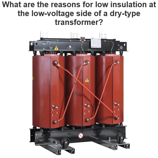
During the installation and debugging of substation electrical equipment, as a core device, the installation and debugging of the transformer are of utmost importance. The following are specific problems that may be encountered during the installation and debugging of the transformer.
1.1.1 Installation Problems
- Position and Fixing: The installation position of the transformer needs to meet the design requirements to ensure it is stable and vertical. Improper installation position or insecure fixing may cause the transformer to vibrate or shift during operation, affecting its normal operation.
- Wiring Issues: The wiring of the transformer must be carried out strictly in accordance with the drawings and specifications. Incorrect wiring may lead to safety hazards such as short - circuits and electric leakage. At the same time, the tightness of the wiring needs to be appropriate. Too loose may result in poor contact, while too tight may damage the wiring terminals.
- Insulation Treatment: During the installation of the transformer, insulation treatment is crucial. Improper selection of insulation materials or non - standard construction may lead to a decline in insulation performance, thereby triggering electrical failures.
1.1.2 Debugging Problems
- Withstand Voltage Test: After the transformer is installed, a withstand voltage test is required to detect its insulation performance. If the test results do not meet the requirements, it may indicate that there are insulation defects inside the transformer or damage occurred during the installation process.
- No - load and Load Tests: The no - load and load tests can be used to detect whether the performance parameters of the transformer meet the design requirements. Abnormal test data may indicate that there are faults inside the transformer or problems occurred during the installation process.
- Temperature and Noise Detection: During the debugging process, the temperature and noise of the transformer also need to be closely monitored. Excessive temperature or noise may indicate problems such as poor heat dissipation and loose iron cores in the transformer.
1.2 Circuit Breaker Faults
1.2.1 Faults during Installation
- Insufficient Line Inspection: Before installing the circuit breaker, the entire line of the circuit breaker needs to be inspected. Inadequate inspection may overlook whether the signals, operation handles, etc. in the line meet the requirements, which may lead to potential hazards in the circuit breaker after installation.
- Insulation Housing Damage: During the installation process, it is necessary to ensure that the insulation housing of the circuit breaker is intact. Any minor damage may lead to a decline in the insulation performance of the circuit breaker, thereby causing safety hazards.
- Screw Fixing Issues: When installing the circuit breaker, the four - corner fixing screws need to be tightened. If the screws are not tightened or tightened too much, it may affect the stability and performance of the circuit breaker.
1.2.2 Faults during Debugging
- Insulation Rod Faults: During the debugging process, the insulation composition and resistance of the insulation rod of the circuit breaker need to be detected [1]. If there are problems with the insulation rod, such as a decline in insulation performance or abnormal resistance values, it will directly affect the normal operation of the circuit breaker.
- Closing and Tripping Coil Faults: During debugging, the insulation resistance and DC resistance of the closing and tripping coils need to be measured. If these parameters do not meet the requirements, it may prevent the circuit breaker from closing or tripping normally.
- Abnormal Closing and Tripping Times: The closing and tripping times of the circuit breaker are important indicators during the debugging process. If the closing and tripping times do not meet the design requirements, it may affect the protection performance of the circuit breaker.
- Excessive Contact Bounce Time: During the debugging process, the bounce time of the contacts when the circuit breaker closes also needs to be measured. Excessive bounce time may lead to increased contact wear, thereby affecting the service life of the circuit breaker.
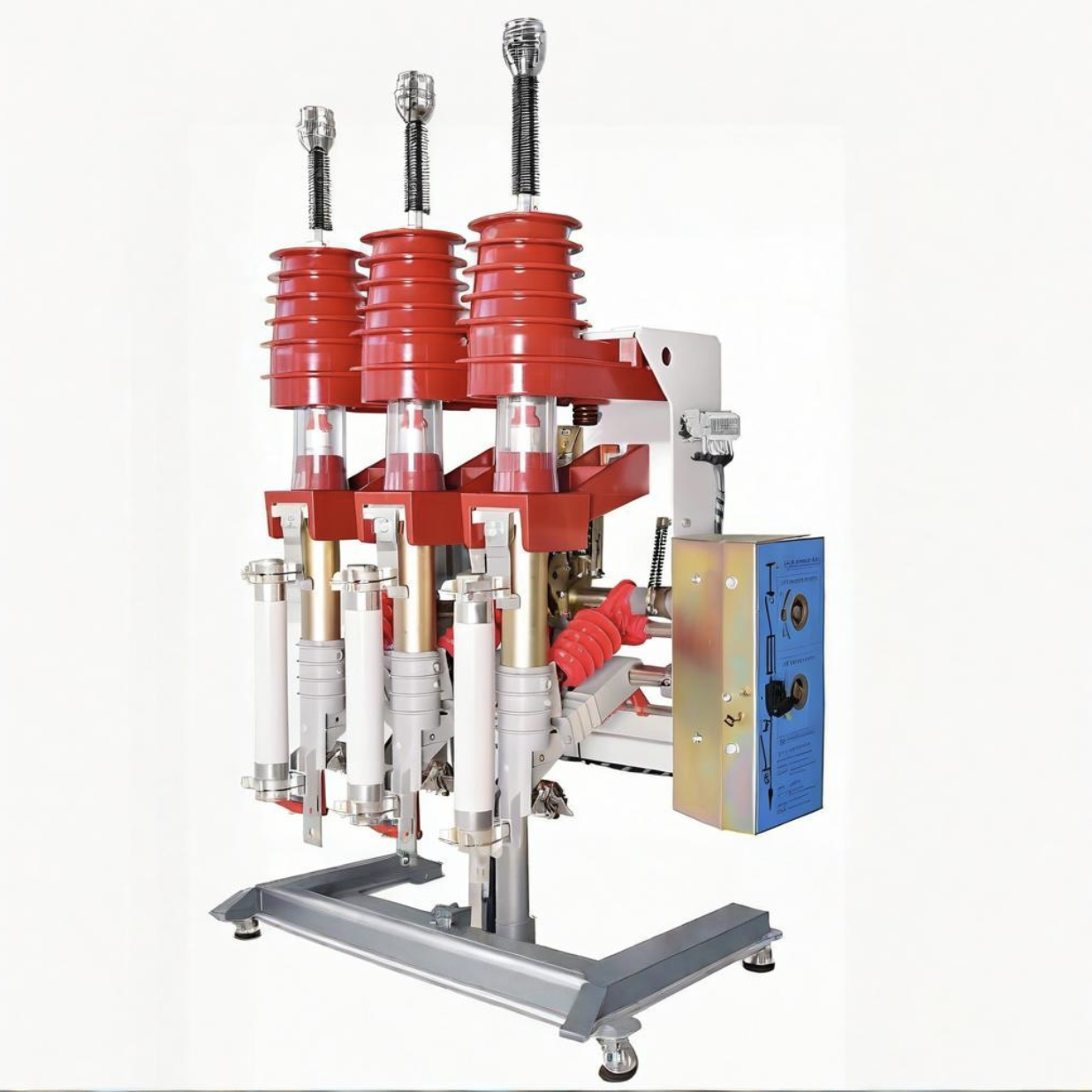
1.3 Disconnector Faults
1.3.1 Faults during Installation
- Porcelain Insulator Fracture: This is usually related to product quality, the overall quality of the disconnector, and the operation method. For example, during the firing process of the porcelain insulator, problems such as under - firing, uneven density, and poor cement bonding may occur due to improper control. In addition, lax quality inspection may also lead to the assembly of individual low - quality porcelain insulators into the product, thereby creating safety hazards during the installation process.
- Overheating of the Conductive Circuit: This is mainly caused by the fatigue and deterioration of the compression spring of the static contact finger, unilateral contact of the static contact finger, and the increase in contact resistance during long - term operation. In addition, poor silver - plating process of the contact, easy wear and copper exposure, dirty contact surface, insufficient insertion of the contact, rusty bolts, etc. may also lead to heating problems.
- Mechanism Problems: This is mainly reflected in operation failures, such as refusal to operate or the switch not being in place. Usually, it is caused by poor sealing or rust and water ingress of the mechanism box, resulting in serious rust of the mechanism, dry lubrication, and increased operation resistance [2].
- Difficult Transmission: This is mainly due to the rust of the transmission system of the disconnector, resulting in large transmission resistance, making it difficult to open or close the switch.
1.3.2 Faults during Debugging
- Failure of Electric Operation: This may be caused by problems in the operation power supply circuit, power supply circuit, or reasons such as fuse fusing, loosening, and abnormal electrical interlocking circuits.
- Incomplete Closing or Non - Synchronous Three - Phase: Such problems are mostly caused by mechanism rust, jamming, and improper maintenance and debugging.
- Heating of the Contact Part: During the debugging process, heating of the contact part may be found. This is usually caused by reasons such as the loosening of the compression spring or screws, oxidation of the contact surface leading to an increase in contact resistance, too small contact area between the blade and the static contact, excessive load operation, and arc - burning of the contact during the closing and opening process or improper force resulting in an incorrect contact position.
1.4 Transformer Faults
1.4.1 Faults during Installation
- Internal Winding Short - Circuit: This is usually caused by the rupture or breakdown of the insulation material between the windings. An internal winding short - circuit will cause the transformer to fail and may even trigger more serious electrical failures.
- Terminal Loosening or Poor Contact: When connecting the transformer, terminal loosening or poor contact will lead to unstable output signals and measurement errors.
- Housing Electric Leakage: This usually occurs in high - humidity and corrosive environments. Electric leakage will not only lead to measurement errors but also pose a safety hazard.
1.4.2 Faults during Debugging
- Ratio Deviation: The ratio of the transformer may deviate from the normal value, which will affect the accuracy of measurement. During the debugging process, a current source with known accuracy needs to be used for testing to ensure the accuracy of the ratio.
- Core Saturation: Under high - current conditions, the core of the transformer may saturate, resulting in distortion and error of the output voltage. During debugging, it is necessary to check whether the output is linearly related to the input current to avoid the problem of core saturation [3].
- Temperature Drift: Temperature changes may cause the performance of the current transformer to drift. Testing the output of the current transformer under different temperature conditions can check for the presence of temperature drift.
- External Magnetic Field Interference: The external magnetic field may interfere with the operation of the current transformer. Testing the output of the current transformer under the condition of no external current can observe whether it is affected by the external magnetic field.
1.5 Lightning Arrester Faults
1.5.1 Faults during Installation
- Improper Installation Position: The installation position of the lightning arrester needs to be carried out strictly in accordance with the regulations. An installation position that is too low or too high may affect its lightning protection effect. In addition, installing the lightning arrester in a place vulnerable to mechanical damage, serious pollution, or chemical corrosion may also lead to a decline in its performance or damage.
- Connection Problems: Poor contact or loosening of the connection wires of the lightning arrester will prevent it from working properly. For example, a too - small cross - sectional area of the connection wires, insecure connection, or corrosion may all lead to failures.
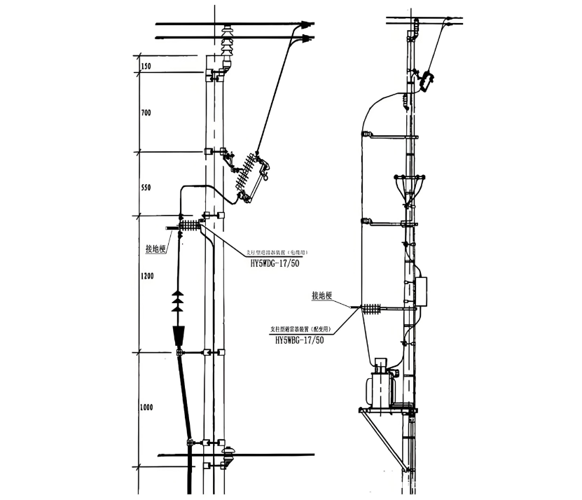
- Grounding Problems: The grounding of the lightning arrester is an important part of its normal operation. An excessive grounding resistance or a broken grounding wire will seriously affect the effect of the lightning arrester. The connection diagram of the lightning arrester is shown in Figure 1.
- Excessive Leakage Current: If the leakage current of the lightning arrester exceeds the specified value during debugging, it may be caused by reasons such as internal moisture, insulation aging, or damage of the lightning arrester. In such cases, timely maintenance or replacement is required.
- Excessive Residual Voltage: After the lightning arrester operates, it should be able to quickly reduce the voltage to a safe level. If excessive residual voltage is detected during debugging, it may be due to the damage or aging of internal components of the lightning arrester. This also calls for maintenance or replacement.
- Insensitive Operation: During the debugging process, if the lightning arrester is found to be insensitive or fails to operate, it may be caused by internal mechanical failures, poor electrical connections, or aging [4]. In this situation, a detailed inspection and repair of the lightning arrester are necessary.
2. Fault Handling in the Installation and Debugging of Substation Electrical Equipment
2.1 Principles of Fault Handling in the Installation and Debugging of Substation Electrical Equipment
- Safety - First Principle: When dealing with faults, the safety of personnel is the top priority. It is essential to strictly abide by safety operation procedures to avoid casualties or further accidents.
- Rapid Response Principle: Once a fault occurs, the staff should respond promptly and handle it in a timely manner. Do not underestimate the fault due to its small - scale or inconspicuous symptoms to ensure the problem is resolved in a timely manner.
- Inspection - Before - Treatment Principle: Before handling a fault, a comprehensive inspection should be carried out first to identify the specific location and cause of the fault, so as to deal with it in a targeted manner and avoid misjudgment or delay in repair time.
- Combination of Repair and Prevention Principle: While handling the fault, experience should be summarized, the root cause of the fault should be identified, and corresponding preventive measures should be taken to avoid the recurrence of similar faults.
2.2 Procedures for Fault Handling in the Installation and Debugging of Substation Electrical Equipment
- Rapid Response Principle: Once a fault occurs, the staff should respond promptly and handle it in a timely manner. Do not underestimate the fault due to its small - scale or inconspicuous symptoms to ensure the problem is resolved in a timely manner.
- Inspection - Before - Treatment Principle: Before handling a fault, a comprehensive inspection should be carried out first to identify the specific location and cause of the fault, so as to deal with it in a targeted manner and avoid misjudgment or delay in repair time.
- Combination of Repair and Prevention Principle: While handling the fault, experience should be summarized, the root cause of the fault should be identified, and corresponding preventive measures should be taken to avoid the recurrence of similar faults.
3. Case Analysis of Faults in the Installation and Debugging of Substation Electrical Equipment
3.1 Common Faults in the Installation and Debugging of Substation Electrical Equipment
- Faults during the Installation of Electrical Equipment
- Improper Location Selection: Unclear construction drawings or changes in on - site conditions may lead to improper selection of equipment installation locations. For example, if the distance between equipment is too close or the installation height does not meet the requirements, it will affect the operational safety of the equipment and future maintenance management.
- Incorrect Wiring: With a large number of electrical equipment and complex wiring, incorrect wiring may occur, resulting in the equipment being unable to operate normally or posing safety hazards.
- Insecure Equipment Fixing: Due to the large weight of the equipment and frequent vibration, the equipment may not be fixed firmly. This not only affects the stability and safety of the equipment but may also damage the equipment.
- Faults during the Debugging of Electrical Equipment
- Improper Insulator Installation: Improper installation of insulators will lead to a decline in the insulation performance of the equipment, making it prone to discharge faults. During the installation process, it is necessary to strictly follow the equipment manual and installation standards.
- Excessive Grounding Resistance: The test of grounding resistance is of great importance as it is directly related to the safe operation of the equipment. Excessive grounding resistance will lead to equipment grounding faults, affecting the safe and stable operation of the equipment.
- Other Common Faults
- Distribution Box Problems: Distribution boxes play an important role in substations and are also equipment types prone to faults during electrical debugging. Faults may manifest as problems with grounding wires, inability to meet specification requirements under repeated operation conditions, and non - standard openings of the distribution box.
- Improper Equipment Grounding: The importance of grounding treatment lies in conducting electricity and improving the overall safety performance of the equipment. Improper grounding may prevent the equipment from operating normally.
- Equipment Conductor Connection Problems: The connectors connecting conductors in electrical equipment are mainly made of aluminum or copper. Due to their different chemical activities, special attention is required during connection.
3.2 Typical Faults in the Installation and Debugging of Substation Electrical Equipment
- Transformer Faults
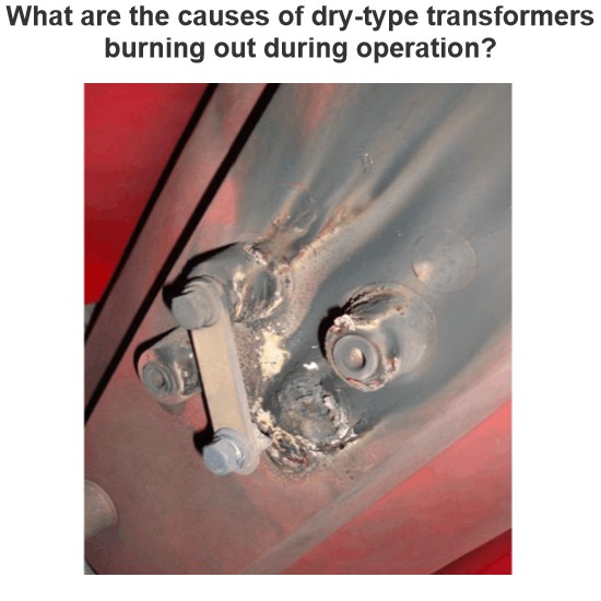
- Overheating: It may be caused by a cooling system failure or overload. It is necessary to check the cooling system and load conditions of the transformer.
- Abnormal Noise: Usually, it is caused by impurities inside the transformer or structural looseness. Cleaning and tightening treatments should be carried out.
- Oil Leakage: It may be caused by the aging or damage of the sealing parts of the insulating oil. It is necessary to check and replace the sealing parts.
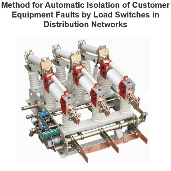
- Switchgear Faults
- Poor Contact: It may be caused by loose wiring or contamination of metal contacts. Cleaning and tightening treatments should be carried out.
- Tripping: It may be caused by improper settings of overload protection devices or equipment failures. It is necessary to check the protection parameters and equipment status.
- Transmission Line Faults
- Insulation Damage: It may be caused by equipment defects, insulation aging, or environmental humidity. Insulation detection and replacement of damaged components should be carried out.
- Electric Leakage: It may be caused by line damage or poor contact. Partial discharge testing and insulation treatment should be carried out.
- Protection Device Faults: Protection devices may experience misoperation or refusal to operate. It is necessary to check the wiring, power supply, and setting parameters of the protection devices.
- Grounding Faults: Problems such as excessive grounding resistance or damaged grounding wires may lead to grounding faults. It is necessary to check the grounding system and grounding resistance.
- Other Faults: Problems with distribution boxes (such as grounding wire problems, non - standard box openings, etc.), improper equipment grounding, and equipment conductor connection problems need to be inspected and repaired according to specific conditions.
3.3 Special Faults in the Installation and Debugging of Substation Electrical Equipment
- Overload Faults: Overload faults are usually caused by excessive load or equipment damage. Such faults are relatively common in substation electrical equipment and are likely to cause equipment overheating and burnout, seriously affecting the normal operation of the power grid system. When dealing with such faults, the first step is to adjust the system load distribution to avoid equipment overload, and then check for any equipment damage and carry out timely repair or replacement.
- Short - Circuit Faults: Short - circuit faults are relatively serious faults in substation electrical equipment. They may be caused by poor internal circuit connections of equipment or damage to the grounding wires of external equipment. Short - circuit faults are likely to cause equipment damage, fires, and other dangerous situations, severely affecting the normal operation of the power grid system. When dealing with such faults, the power supply should be quickly cut off, the cause of the short - circuit should be checked, and repairs should be carried out.
- Grounding Faults: Grounding faults may be caused by excessive grounding resistance, damaged grounding wires, etc. Such faults will affect the normal operation of the equipment and may trigger dangerous situations such as fires. When dealing with such faults, it is necessary to check whether the grounding device is intact and eliminate problems such as poor contact of the grounding resistance to ensure that the grounding resistance meets the requirements.
- Insulation Faults: Insulation faults are usually caused by equipment defects, insulation aging, environmental humidity, etc. When insulation faults occur, the equipment often cannot operate normally, and in severe cases, it may cause damage to the staff and equipment. When dealing with such faults, insulation detection and maintenance should be carried out to improve the insulation level of the equipment and prevent the occurrence of insulation faults.
4. Abnormal Phenomena in the Installation and Debugging of Substation Electrical Equipment
- Distribution Box Installation Faults: Gaps between the distribution box and the ground may be due to the inability of the grounding wire to meet the specification requirements under repeated operation conditions; non - standard openings of the distribution box body, with too many welding openings, resulting in damage to the protective paint of the box body; limited space in the distribution box, affecting manual operation.
- Conductor Quality Problems: The color and quantity of conductors do not meet the requirements, which may easily cause confusion for installers. For example, the neutral wire, live wire, and ground wire have the same color, creating a safety hazard.
- Conduit Laying Problems: The conduits are too short or the wires are exposed, and there is an overlapping phenomenon between the distribution box and the concealed pipeline. Construction workers do not properly control the depth of the conduits buried in the wall or ground, resulting in insufficient reserved space, which brings difficulties to wire crossing and threading work.
- Improper Insulator Installation: Insulators are not installed in accordance with the specifications, resulting in a decline in the insulation performance of the equipment and possibly triggering discharge faults.
- Excessive Grounding Resistance: The measured value of the grounding resistance exceeds the specified standard, which may affect the safe and stable operation of the equipment.
- Poor Contact at Busbar Joints: Poor installation of busbar joints leads to unstable operation of the equipment and may even cause serious consequences such as fires.
- Transformer Faults: Problems such as overheating, abnormal noise, and oil leakage in transformers may be related to their cooling systems, internal impurities, or the sealing performance of insulating oil.
- Switchgear Faults: Phenomena such as poor contact and tripping in switchgear may be related to the firmness of wiring, the cleanliness of metal contacts, or the working state of overload protection devices.
- Transmission Line Faults: Faults such as insulation damage and electric leakage in transmission lines require timely insulation resistance testing and partial discharge testing, and replacement of damaged insulation parts.
- Protection Device Faults: Protection devices may experience faults such as misoperation or non - operation during the electrical installation and debugging process. It is necessary to check the setting parameters and working state of the devices.
For these abnormal phenomena, strict quality control and technical inspection are required during the installation and debugging process to promptly detect and handle problems, ensuring the normal operation and safe and stable operation of substation electrical equipment.
5. Conclusion
The electrical installation and debugging of substations are key links to ensure the stable operation of the power system. This study has in - depth explored the common faults and their handling methods during this process. During the electrical installation and debugging process, every link must be highly emphasized. Technical training and quality control should be strengthened, and the professional level of installation and debugging personnel should be improved. At the same time, a perfect fault prevention and handling mechanism should be established to ensure that faults can be quickly and accurately located and solved. Through scientific and effective fault handling, the reliability and safety of substation electrical equipment can be significantly improved, thus ensuring the normal operation of the entire power system.