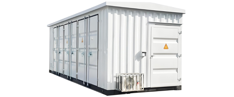
The influence of front-wiring protection devices on the application of prefabricated cabins mainly focuses on three aspects: the layout of the switchgear cabinets, the form of cabin combination in the prefabricated cabin, and the workload of on-site construction. When the development of front-wiring devices is not perfect, the traditional switchgear cabinet structure is adopted. For example, the 220kV Qingzhu Substation in Anhui uses a single-cabin single-row mode, and the 110kV Weicheng Substation in Hubei uses a double-cabin double-row mode. In these two modes, the number of switchgear cabinets that can be placed inside the cabin is relatively small.
To improve the space utilization rate inside the cabin, subsequent projects have also attempted the single-cabin double-row mode. For instance, the 220kV Dashi Substation in Chongqing adopts the single-cabin double-row mode, and the ±800kV Lingzhou Converter Station adopts the single-cabin double-row mode with increased cabin dimensions. The information such as the cabin dimensions and on-site construction volume of these four projects is statistically summarized as follows.
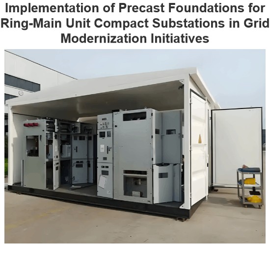
The single-cabin double-row mode can accommodate nearly twice as many switchgear cabinets as the single-cabin single-row and double-cabin double-row modes. In addition, it has advantages such as no need for on-site splicing, no need for wiring inside the cabin, and low cabin cost. However, in the single-cabin double-row mode, equipment maintenance can only be carried out by opening the door on the side wall of the cabin or increasing the size of the cabin. Maintenance outside the cabin cannot meet the all-weather maintenance requirements; increasing the cabin size not only increases the transportation cost but also has higher requirements for the passability of the road.
Currently, the dimensions of switchgear cabinets inside the cabin include 800×600×2260, 600×600×2260, 600×900×2260, etc. When placing switchgear cabinets in prefabricated cabins of the same specification, reducing the size of the switchgear cabinets can effectively increase the number of cabinets that can be placed.
Inside the secondary equipment cabin, various cables such as power cables, optical cables, and patch cables need to be laid out. There are mainly three cable layout schemes inside the cabin: setting a wiring rack on the top of the cabin, setting a wiring rack at the bottom of the cabin, and combining the two. In all three of these methods, the switchgear cabinet structure is used inside the cabin, and the cable layout work needs to be carried out after the switchgear cabinets are in place.
In addition, the cables are interspersed between the structures of the cabin and the switchgear cabinets, which causes inconvenience for subsequent cable maintenance work.The more commonly used scheme of setting a cable interlayer at the bottom of the cabin requires that during the cable maintenance process, the anti-static floor must first be lifted, and then operations can be carried out in a narrow space. This leads to a large workload and a long construction period.
The long-term expansion and reconstruction work inside the secondary equipment cabin mainly adopts the scheme of adding new switchgear cabinets later and then connecting the cables, or placing the empty cabinets in position in advance and carrying out the installation and wiring work of the equipment inside the cabinets during the reconstruction period. The former has a high work intensity, and the latter is limited by the narrow space inside the cabin, resulting in a long reconstruction period.
As can be seen from the analysis in Sections 1.1-1.4, the factors affecting the space utilization rate and operation and maintenance convenience inside the secondary equipment cabin mainly focus on the structure forms of the front-wiring devices and the switchgear cabinets. Given that the front-wiring devices have been gradually matured and popularized, optimization research should be carried out on the structure forms of the switchgear cabinets. In addition, research on the convenience of operation and maintenance work for the equipment inside the cabin is also required to achieve efficient and quick operation and maintenance work.
Aiming at the above problems, an optimized scheme for switchgear cabinets based on the integrated structural layout is proposed to solve the problems of low space utilization rate inside the cabin and difficulty in installing switchgear cabinets into the cabin. A research and design of an open cable layout scheme is proposed to solve the problem of difficult installation and maintenance of optical and power cables.
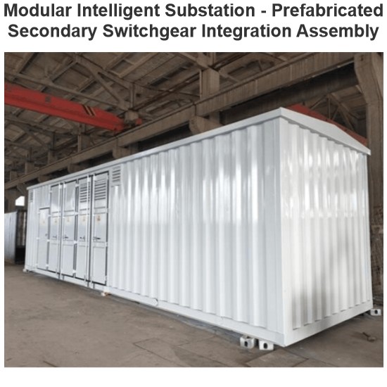
Taking the Type III cabin as an example, its external dimensions are 12200×2800×3133, and the anti-static floor is 250mm thick.
The net height inside the cabin is 2670mm. According to the functional zoning, the height inside the cabin is divided into three parts from bottom to top: the height of the anti-static movable floor, the height of the integrated structure, and the height of the attached installation components. After removing the height of the anti-static movable floor, the remaining height is 2420mm. Referring to the height of traditional switchgear cabinets, the height of the integrated structure is allocated as 2300mm, and the height of the attached components is 120mm.
In traditional front-wiring switchgear cabinets, the device terminals are horizontally arranged and installed at the bottom of the cabinet, and the number of installations is limited. To facilitate the subsequent operation and maintenance work of the equipment and shorten the connection path between the device and the terminals, the terminals are vertically arranged on the right side of the device.
To meet the installation depth requirements of equipment from different manufacturers, the depth of the structural unit is designed with reference to the depth of traditional switchboards, which is 600mm. At the same time, considering that the depth is reduced after canceling the cabinet door and taking necessary anti-misoperation measures, the depth of the structural unit is 550mm.
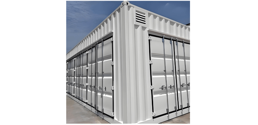
Through the above analysis, the dimensions of a single structural unit inside the prefabricated cabin are 2300×700×550. After using this size structure, the space layout of the switchgear cabinets inside the cabin can achieve the maximum utilization rate.
Inside the structural unit, referring to the existing installation method of switchgear cabinet equipment, it is divided into three parts from top to bottom: the air switch installation area, the equipment installation area, and the accessory installation area. Among them, the equipment installation area is divided into the device installation area and the device maintenance area from left to right.
To increase the number of equipment installed inside a single structure, first, the heights of the equipment to be installed inside the structure are counted. The protection device is 4U or 6U high, and the switch and the cable coiling rack are mostly 1U high. Taking the installation of 2 switches in the interval above the 220kV voltage level as an example, a height of 4U can meet the installation requirements of 2 switches and 1 cable coiling rack.
The number of hard pressure plates and buttons of the intelligent device is configured as 2 hard pressure plates and 1 reset button for the protection device; and 3 hard pressure plates and 1 reset button for the measurement and control device. The 4U installation panel can arrange at most 2 rows, with 9 hard pressure plates or buttons in each row. Therefore, the 4U panel can meet the installation requirements of 6 protection devices or 4 measurement and control devices.
According to the analysis of the visual field of maintenance personnel in a standing position, the visual point of a person is approximately between 1.5-1.6m, and the best visual field is within the range of 10° above and below the horizontal visual point, that is, the installation height of the device is between 1215-1920mm, and the height is 700mm. According to the above height requirements and combined with the analysis data, when the "6-module" device arrangement method is adopted, the best operation experience can be obtained.
The open maintenance channel scheme includes three parts: the inside of the structural unit, the area between the structural units of the same row, and the wiring channel inside the cabin.
- Open maintenance channel inside the structural unit. A device maintenance area of the same height is set on the right side of the device installation area to place the terminal strip. An optical and electrical separation cable layout scheme is adopted, with the patch cables and communication cables vertically installed on the left side and the power cables vertically installed on the right side.
- Open maintenance channel between structural units of the same row. Use the "7"-shaped column structure so that the columns of the structural units of the same row can form a continuous and open cable layout channel. Move the optical and power cable layout channel of the same row below the anti-static floor to above the anti-static floor.
- Cable crossover channel inside the cabin (between two rows of structural units). A small number of wiring racks are set below the anti-static floor between the two rows of structures. When carrying out the cable maintenance work between the two rows, only a small number of anti-static floors in the width direction of the cabin need to be lifted, and personnel can stand on other anti-static floors to carry out the maintenance work on the cables in the interlayer. In addition, the anti-static floor at the top of the wiring channel can be made of transparent conductive glass or marked with signs to achieve quick positioning.
This article conducts research on the existing problems of prefabricated cabin products and innovatively proposes a structure that is integrated with the prefabricated cabin, achieving the expected results. Through research, the following conclusions are obtained:
- The integrated structure replaces the traditional switchgear cabinets, and the number of cabinets that can be placed inside the cabin increases by 12-17%. If the position of the cabin door is adjusted, it can increase by 28-37%.
- The "6-module" arrangement method is adopted for the layout of the equipment area inside the structure, which improves the space utilization rate inside the structure and facilitates observation and operation.
(3) The design of the full-path open cable layout channel greatly reduces the workload and difficulty of cable operation and maintenance.