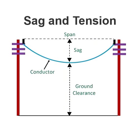
A transmission line serves the crucial function of conveying electrical power from generating substations to diverse distribution units. It effectively transmits voltage and current waves from one end to the other. Structurally, a transmission line consists of a conductor that maintains a consistent cross - section throughout its length. Meanwhile, air functions as the insulating or dielectric medium situated between the conductors, playing a vital role in preventing electrical leakage and ensuring the safe and efficient transmission of electricity.

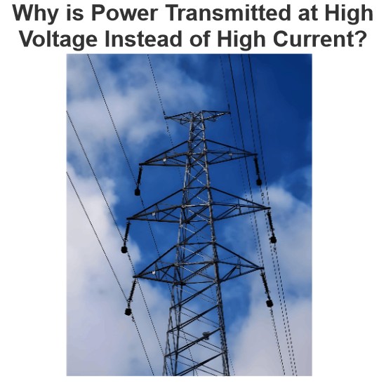
For safety considerations, a significant distance is maintained between the transmission line and the ground. Electrical towers are employed to support the conductors of the transmission line. These towers are constructed from steel to endow the conductors with high strength and stability, ensuring reliable power transmission. When it comes to transmitting high - voltage electricity over long distances, high - voltage direct current (HVDC) is often utilized in transmission lines due to its unique advantages in minimizing power losses and improving transmission efficiency.
Parameters of Transmission Line
The performance of a transmission line hinges on its inherent parameters. A transmission line primarily has four key parameters: resistance, inductance, capacitance, and shunt conductance. These parameters are evenly distributed along the entire length of the line, which is why they are also referred to as the distributed parameters of the transmission line. Each of these parameters plays a crucial role in determining how electrical signals and power are transmitted, affecting aspects such as power loss, voltage drop, and signal integrity.
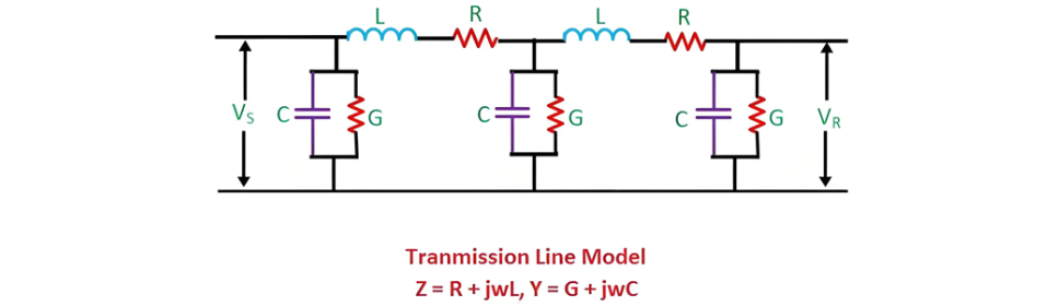
The inductance and resistance combine to form the series impedance, while the capacitance and conductance together constitute the shunt admittance. Below, some of the critical parameters of a transmission line are explained in detail:
Line Inductance
When current flows through a transmission line, it induces a magnetic flux. As the current within the transmission line fluctuates, the magnetic flux also changes accordingly. This variation in magnetic flux leads to the induction of an electromotive force (emf) in the circuit. The magnitude of the induced emf is directly proportional to the rate of change of the magnetic flux. The emf generated in the transmission line opposes the flow of current through the conductor, and this characteristic is known as the line inductance.
Line Capacitance
In transmission lines, air serves as the dielectric medium. This dielectric medium effectively forms a capacitor between the conductors, which has the ability to store electrical energy and thus increases the line's capacitance. Capacitance of a conductor is defined as the ratio of the charge present to the potential difference across it.
In short transmission lines, the effect of capacitance can often be considered negligible. However, in long - distance transmission, it becomes one of the most critical parameters. It significantly impacts various aspects of the electrical system, including its efficiency, voltage regulation, power factor, and overall stability.
Shunt Conductance
Air acts as the dielectric medium between the conductors in a transmission line. When an alternating voltage is applied to the conductors, due to imperfections in the dielectric, a certain amount of current flows through the dielectric medium. This current is referred to as the leakage current. The magnitude of the leakage current is influenced by atmospheric conditions and environmental factors such as moisture and surface deposits. Shunt conductance is defined as the flow of this leakage current between the conductors. It is uniformly distributed along the entire length of the line, represented by the symbol "Y", and is measured in Siemens.
Performance of Transmission Lines
The concept of transmission line performance encompasses the calculation of various parameters, including the sending - end voltage, sending - end current, sending - end power factor, power losses within the lines, transmission efficiency, voltage regulation, as well as the limits of power flow during both steady - state and transient conditions. These performance calculations play a vital role in electrical system planning. Among these, some key parameters are elaborated upon below:
Voltage Regulation
Voltage regulation is defined as the difference in the magnitude of the voltage between the sending end and the receiving end of a transmission line.

Important Points
Admittance is a crucial electrical parameter that quantifies the ability of an electrical circuit, or more specifically, the efficiency of a transmission line, to facilitate the unobstructed flow of alternating current (AC). Its SI unit is the Siemens, and it is commonly denoted by the symbol "Y". In essence, a higher admittance value indicates that the circuit or transmission line offers less opposition to the flow of AC, enabling current to pass through more freely.
Conversely, impedance is the reciprocal of admittance. It measures the total opposition that a transmission line presents to the flow of AC. When AC traverses a transmission line, impedance accounts for the combined effects of resistance, inductive reactance, and capacitive reactance, which together create a hindrance to the current flow. Impedance is measured in ohms and is represented by the symbol "Z". A higher impedance value implies greater difficulty for the AC to flow through the line, resulting in reduced current levels and potential power losses.