Types of HVDC Systems and MTDC Configurations

Edwiin
05/07/2025
High - Voltage Direct Current (HVDC) System Configurations
High - Voltage Direct Current, commonly abbreviated as HVDC, is a highly efficient method for long - distance power transmission, significantly reducing power losses compared to traditional alternating - current (AC) transmission. The HVDC system can be implemented in various configurations, each tailored to specific operational requirements. This article provides a concise overview of the main types of HVDC system configurations.
Back - to - Back HVDC Systems
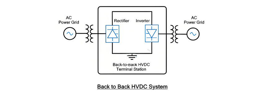
In a back - to - back (B2B) HVDC configuration, both the rectifier and the inverter, which are key components of the converter, are housed within the same terminal station. These two converter elements are directly connected back - to - back with one another. The primary function of this configuration is to connect two separate AC power systems. It achieves this by first converting the incoming AC power into DC through the rectifier and then promptly transforming the DC power back into AC using the inverter.
Back - to - Back HVDC Systems (Continued)
The back - to - back HVDC setup is installed within a single room and serves to interconnect two asynchronous AC power systems. Given the direct back - to - back connection of the rectifier and inverter, there is no need for a DC transmission line. To minimize the number of thyristors connected in series, the intermediate DC voltage is intentionally maintained at a low level. Meanwhile, the current rating of this configuration can reach several thousand amperes.
This type of HVDC system is particularly useful for linking two asynchronous AC power systems in the following scenarios:
- When the two AC systems or power grids operate at different frequencies.
- When the two systems have the same frequency but exhibit a phase difference.
Two - Terminal HVDC System
In a two - terminal HVDC configuration, there are two distinct terminal stations, each functioning as a converter station. One station houses a rectifier, while the other contains an inverter. These two terminals are connected by an HVDC transmission line, enabling the efficient transmission of electrical power over long distances. This setup is designed to overcome the limitations of traditional AC transmission for long - haul power transfer, leveraging the advantages of DC power to minimize power losses and enhance transmission efficiency across vast geographical areas.

The two - terminal HVDC system features a direct connection between two points without any parallel transmission lines or intermediate taps along the transmission line. This characteristic gives rise to its alternative name, point - to - point power transmission. It is ideally suited for power supply applications between two locations that are geographically distant from each other.
One of the notable advantages of the two - terminal HVDC system is its lack of requirement for an HVDC circuit breaker. In the event of maintenance or when clearing faults, the AC circuit breakers on the AC side can be utilized to de - energize the DC line. Compared to DC circuit breakers, AC circuit breakers have a simpler design and come at a lower cost, making the two - terminal HVDC system more economical and easier to maintain.
Multi - Terminal DC (MTDC) System
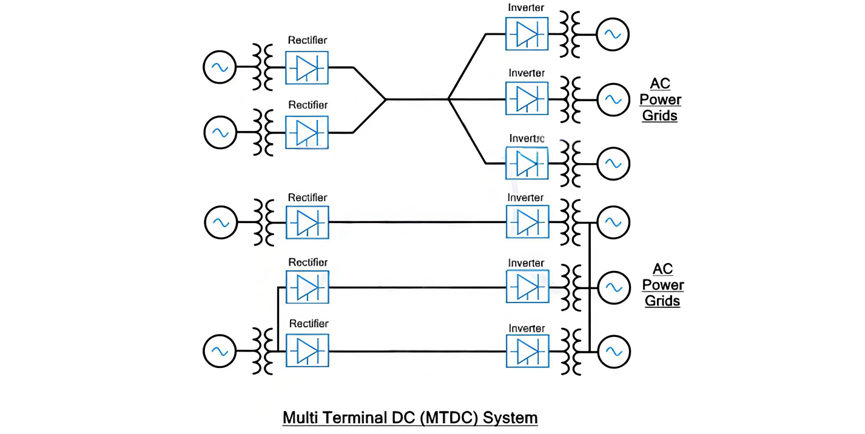
The Multi - Terminal DC (MTDC) system represents a more complex HVDC configuration. It employs multiple transmission lines to establish connections between more than two points. This setup comprises several terminal stations, each equipped with its own converter, all interconnected by an HVDC transmission line network. Within this network, some converters function as rectifiers, converting AC power to DC, while others operate as inverters, transforming DC power back into AC for distribution to loads. A fundamental principle of the MTDC system is that the total power supplied by the rectifier stations must equal the combined power received by the inverter (load) stations, ensuring a balanced and efficient power flow across the interconnected network.
Multi - Terminal DC (MTDC) System (Continued)
The MTDC network is analogous to an AC grid in terms of its flexibility, but it offers a unique advantage: the ability to precisely control power flow within the DC distributed network. However, this enhanced functionality comes at the cost of increased complexity, making the MTDC system significantly more intricate than a two - terminal HVDC configuration.
In an MTDC setup, relying on AC circuit breakers on the AC side is not feasible. Unlike in a two - terminal system, using an AC circuit breaker would de - energize the entire DC network instead of isolating only the faulty or maintenance - required line. To address this, the MTDC system necessitates multiple DC switchgear components, such as circuit breakers. These specialized DC circuit breakers are designed to safely de - energize circuits or isolate specific sections during maintenance operations or when clearing faults, ensuring the stability and reliability of the network.
Maintaining system balance is crucial in an MTDC system. The total current supplied by the rectifier stations must precisely match the current consumed by the inverter stations. When there is a sudden surge in power demand from any inverter station, the DC power output needs to be ramped up accordingly to meet the increased load. During this process, it is essential to closely monitor and control both the supplied voltage and the operation of the inverters to prevent overloading, which could lead to system failures.
One of the key strengths of MTDC systems is their reliability during forced outages. In the event of an unexpected power failure at one of the generation stations, the system can quickly re - route power through alternative converter stations, minimizing disruption to the overall power supply.
Applications of MTDC
- Renewable Energy Integration: Facilitates the connection of multiple DC - based renewable energy farms to various power grids, enabling the efficient distribution of clean energy.
- Offshore Wind Power: Enables the connection of multiple offshore wind farms to the onshore power grid, overcoming the challenges associated with transmitting large amounts of power over long distances from remote offshore locations.
- Bulk Power Transfer: Allows for the transfer of large - scale power from multiple remote AC generating stations to multiple load centers, optimizing power distribution across vast regions.
- Grid Interconnection: Permits the interconnection between two asynchronous AC power systems, enhancing grid stability and power exchange capabilities.
- Power Reallocation: Enables power supply reallocation in the event of power failures at individual generating stations, ensuring continuous power delivery to consumers.
- AC Network Support: Can provide additional power to heavily loaded AC networks by using a single rectifier and multiple inverters to inject power into the AC grid, alleviating congestion and improving overall grid performance.
- Flexible Power Tapping: Offers the flexibility to tap power at multiple points within the network, adapting to diverse power demands and distribution requirements.
MTDC systems can be categorized into two primary types:
Series MTDC System
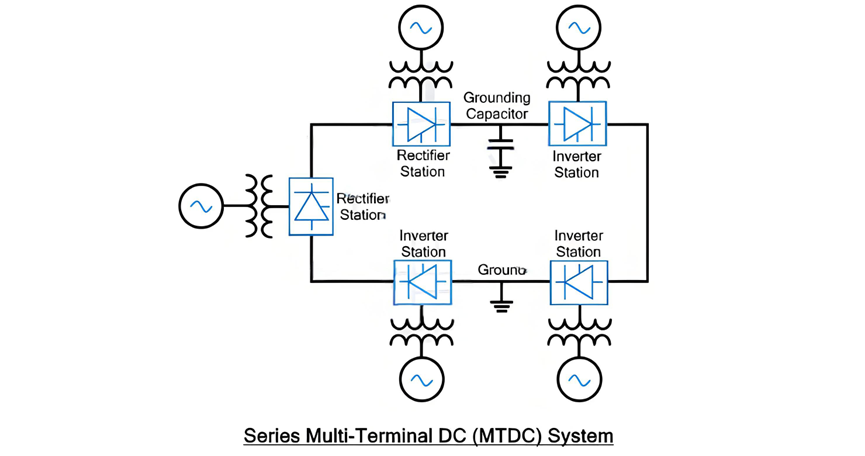
In a series MTDC configuration, multiple converter stations are connected in series, much like components in an electrical series circuit. A defining characteristic of this setup is that the current flowing through each converter station remains identical, as it is set by one of the stations. However, the voltage drop is distributed among the converter stations, with each station experiencing a portion of the total voltage drop across the series - connected network.
Series MTDC System (Continued)
The series MTDC system can be regarded as an extended version of the two - terminal HVDC system, incorporating multiple converter stations connected in series, as illustrated in the accompanying diagram. Typically, the converter stations in a series MTDC setup have a lower capacity compared to those utilized in parallel MTDC systems.
This system commonly employs monopolar DC links, where the DC line is grounded at only one specific point. To safeguard against transient electrical surges, a grounding capacitor can be installed at other points along the line as an additional protective measure.
Insulation coordination in the series MTDC system presents significant challenges due to the varying DC voltages at each station. The power flow control mechanism in the series MTDC system is more intricate compared to that of the parallel MTDC system. In a parallel MTDC system, power flow can be regulated by injecting current into specific lines, whereas in the series MTDC system, power flow control relies on adjusting the voltage at each terminal station.
Power flow reversal in a series MTDC system can be readily achieved using both Voltage Source Converters (VSC) and Current Source Converters (CSC). However, when a fault occurs or scheduled maintenance is required for a particular line, the entire DC network will experience a blackout. Similar to the two - terminal HVDC system, AC - side circuit breakers are employed to de - energize the DC network. Expanding the series MTDC system also poses difficulties. Installing new terminal stations necessitates a complete blackout of the network, as the ring - shaped DC network must be split at the installation point, disrupting power supply to all other stations along the path.
Parallel MTDC System
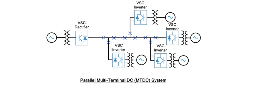
In a parallel MTDC system, multiple converter stations functioning as inverters or load stations are connected to a single converter station acting as a rectifier. This rectifier station supplies power to the entire DC network. Analogous to a parallel electrical circuit, the voltage remains constant across all inverter or load stations, with its value set by one of the converter stations. In contrast, the current supply varies according to the power demand at each station. To maintain a balanced current supply, the current is dynamically adjusted in response to the power requirements of individual load stations. Generally, the terminal stations in a parallel MTDC system have a higher capacity than those in a series MTDC network.
Parallel MTDC System (Continued)
Power reversal in a parallel MTDC system can be accomplished through either voltage reversal or current reversal methods. When using voltage reversal, which is typically associated with Current Source Converter (CSC) - based terminal stations, it has an impact on all converter stations. As a result, a highly sophisticated control and communication system must be implemented among these converters to manage this effect. On the other hand, if power reversal is achieved using the current reversal technique, which is often associated with Voltage Source Converter (VSC) - based terminal stations, the process is much more straightforward to execute. This is the primary reason why VSCs are favored over CSCs in parallel MTDC systems.
In a VSC - based MTDC system, since the voltage remains constant, the power rating of the terminal station is determined by the current ratings of the valve converter. This configuration offers a significant advantage in terms of power flow control within the DC network. It can precisely regulate the power flow by injecting current into specific lines, which is a more convenient approach compared to the power control mechanism in series systems that rely on voltage control at each station.
One of the most notable features of the parallel MTDC system is its resilience in the face of faults. If a fault occurs in any of the terminal stations, the remainder of the DC network remains unaffected. However, to isolate the specific DC lines associated with the faulty station, a separate DC circuit breaker is required. Additionally, during the expansion of the DC network, there is no need to interrupt the power supply. This is because new terminal stations can be installed in parallel with the existing lines, ensuring seamless integration without disrupting the ongoing power distribution.
Another advantage of the parallel MTDC system is its relatively simple insulation coordination compared to a series system. Due to the constant voltage across the network, the insulation requirements are more straightforward to manage.
The parallel MTDC system can be further classified into two categories:
Radial MTDC System
The radial MTDC system is a specific type of parallel MTDC configuration. In this setup, if there is a break in a transmission line or the removal of one link, it will lead to the interruption of power supply to one or more converter stations. This characteristic makes the radial MTDC system somewhat vulnerable to single - point - of - failure scenarios, as any disruption in the transmission line can have a direct impact on the power supply to certain parts of the network.
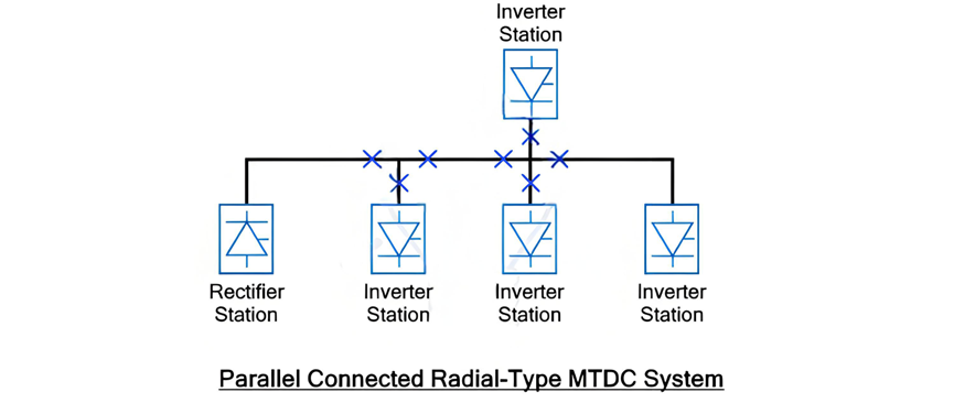
The provided figure depicts a configuration where four inverter stations are connected to a single rectifier station. In this setup, it is evident that if there is a break in any one of the lines, it will inevitably result in the interruption of power supply to at least one terminal station. This vulnerability makes the radial MTDC system less reliable when compared to the Mesh or Ring type MTDC systems.
Mesh (Ring) MTDC System
In a Mesh or Ring MTDC system, the inverter (load) stations are interconnected with a single rectifier station in a mesh or ring - like formation. One of the key advantages of this configuration is that even if there is a break in a single transmission line or the removal of one link, it does not lead to the interruption of power supply to any of the inverter stations. The subsequent figure clearly illustrates such a mesh or ring MTDC system. This inherent resilience to line failures makes the Mesh or Ring MTDC system a more reliable option for power transmission and distribution in certain applications, as it can better withstand disruptions and ensure continuous power supply to the connected load stations.
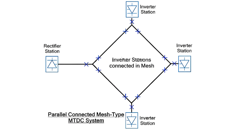
As illustrated, in a mesh or ring - type MTDC system, the removal of any single link does not disrupt the power supply to any converter station. Instead, the electrical power is automatically rerouted through alternative links within the network. This seamless redirection is made possible by the interconnected nature of the mesh or ring configuration. However, it is crucial to note that these alternative links must be meticulously designed to handle the increased power transmission while minimizing power losses.
The absence of power interruptions in the mesh - type MTDC system is a significant advantage. It ensures a continuous and stable power supply, even in the face of unexpected link failures. Consequently, a parallel - connected mesh - type MTDC system offers superior reliability compared to its parallel - connected radial - type counterpart. The radial system's susceptibility to power outages due to single - link disruptions pales in comparison to the mesh system's robust ability to maintain power flow under similar circumstances, making the mesh or ring - type MTDC system a preferred choice for applications where uninterrupted power delivery is of utmost importance.
Topics