Electrical Transmission Networks – EHV and HV Overhead Lines

Edwiin
05/06/2025

Topics

Classification of Electric Power Distribution Network Systems
The typical electric power system network is categorized into three main components: generation, transmission, and distribution. Electric power is produced in power plants, which are often located far from load centers. As a result, transmission lines are employed to deliver power over long distances.To minimize transmission losses, high-voltage power is used in transmission lines, and the voltage is reduced at the load center. The distribution system then delivers this power to end-users.Types
Edwiin
06/05/2025

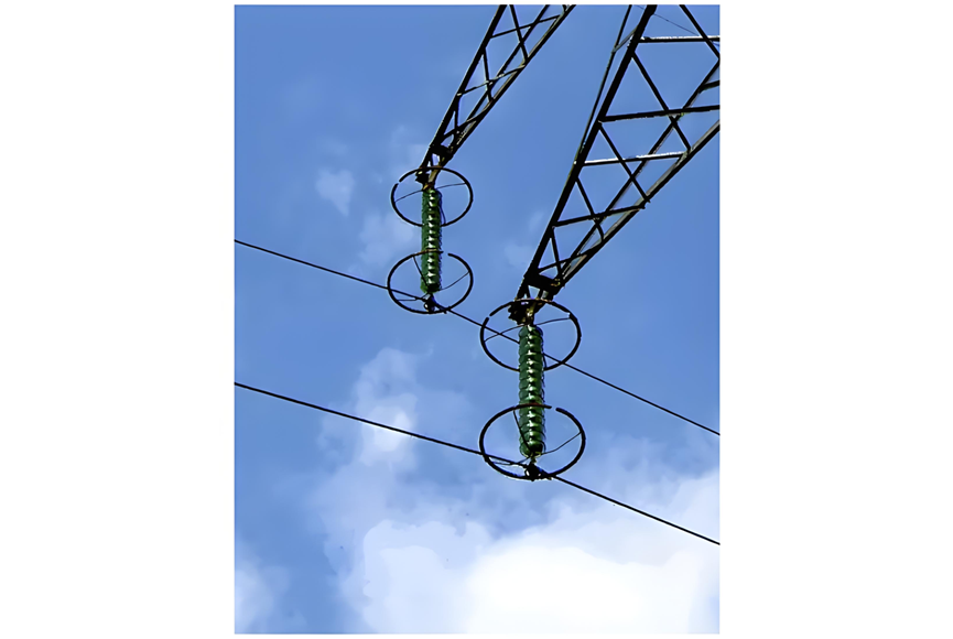
Why is the Ground Wire Always Positioned Above the Overhead Power Lines?
Ground Wire in Overhead Transmission LinesThe ground wire (also called earth wire or OPGW) installed above phase lines in overhead transmission lines acts as a key protective and safety component. It provides lightning protection, ground fault defense, and helps prevent electrical system disruptions.In overhead transmission lines, positioning the ground wire above phase lines serves specific safety and performance purposes. Referred to as a "shield wire" or "static wire," this configuration has
Edwiin
06/04/2025

What is the Power Angle in a Power Transmission Line?
The power angle, denoted by δ, is the phase angle difference between two voltage levels in a power transmission line. Specifically, it represents the angular discrepancy between the sending-end voltage phasor and the receiving-end voltage (or between voltages at two bus points). In simpler terms, it quantifies the phase shift between voltage and current waveforms in the transmission line.Also referred to as the torque angle or load angle, this parameter is critical for two key reasons: it
Edwiin
06/04/2025

Permanent Magnet Moving Coil or PMMC Instrument
DefinitionInstruments that utilize a permanent magnet to generate a stationary magnetic field within which a coil moves are known as Permanent Magnet Moving Coil (PMMC) instruments. They operate on the principle that torque is exerted on a moving coil situated in the magnetic field of a permanent magnet. PMMC instruments provide accurate results for direct current (DC) measurements.Construction of PMMC InstrumentThe moving coil and the permanent magnet are the key components of a PMMC instrument
Edwiin
05/30/2025


