The typical electric power system network is categorized into three main components: generation, transmission, and distribution. Electric power is produced in power plants, which are often located far from load centers. As a result, transmission lines are employed to deliver power over long distances.
To minimize transmission losses, high-voltage power is used in transmission lines, and the voltage is reduced at the load center. The distribution system then delivers this power to end-users.
Types of Electric Power Distribution Systems
The distribution system can be classified based on several criteria:
-
Nature of Supply:
- AC Distribution System: Most consumers require AC power, making it the standard for generation, transmission, and distribution. AC voltage can be easily adjusted using transformers, enabling efficient step-up and step-down operations.
- DC Distribution System: Less common but used in specific applications.
-
Connection Type:
- Radial System
- Ring System
- Interconnected System
-
Construction Type:
- Overhead System
- Underground System
Classification by Supply Nature
Electric power exists in two forms: AC and DC. The distribution system aligns with these types. The AC distribution system is further divided by voltage level:
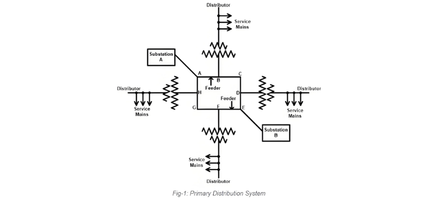
- Primary Distribution System: Operates at higher voltages (e.g., 3.3 kV, 6.6 kV, 11 kV) using a three-phase three-wire configuration. It supplies large consumers like industries or commercial complexes, with step-down transformers near premises reducing voltage to usable levels.
- Secondary Distribution System: Delivers power at lower, consumer-friendly voltages.
The primary distribution system's typical layout is illustrated below, showcasing its role in high-voltage power delivery before final voltage conversion.
The secondary distribution system delivers power at the utilization voltage level. It begins where the primary distribution system ends—typically at a transformer that steps down 11 kV to 415 V for direct distribution to small consumers.
Most transformers in this stage feature a delta-connected primary winding and a star-connected secondary winding, which provides a grounded neutral terminal. This configuration enables the secondary distribution system to use a three-phase four-wire setup.
- Single-Phase Supply: Derived by connecting any one phase to the neutral terminal, yielding 230 V or 120 V (depending on national standards). This is commonly used for residential homes and small shops.
- Three-Phase Supply: Utilized by small industries, flour mills, and similar consumers, who connect to the R, Y, B phase terminals and neutral (N) for three-phase power.
The layout of a secondary distribution network is illustrated below, demonstrating how voltage is adapted for end-user applications.

DC Distribution System
While most power system loads are AC-based, certain applications require DC power, necessitating the use of a DC distribution system. In such cases, generated AC power is converted to DC via rectifiers or rotary converters. Key applications for DC power include traction systems, DC motors, battery charging, and electroplating.
The DC distribution system is categorized by its wiring configuration:
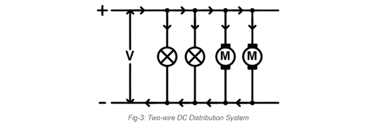
Two-Wire DC Distribution System
This system utilizes two wires: one at positive potential (live wire) and the other at negative or zero potential. Loads (such as lamps or motors) are connected in parallel between the two wires, suitable for devices with two-terminal configurations. A schematic of this setup is shown below.
Three-Wire DC Distribution System
Three-Wire DC Distribution System
This system employs three wires: two live wires and one neutral wire, offering the key advantage of providing two voltage levels. Suppose the live wires are at +V and -V, with the neutral at zero potential. Connecting a load between one live wire and neutral yields V volts, while connecting across both live wires provides 2V volts.
This configuration allows high-voltage loads to connect across the live wires and low-voltage loads to connect between a live wire and neutral. The connection diagram for a three-wire DC distribution system is illustrated below.

Distribution System Classification by Connection Method
The distribution system is categorized into three types based on connection methodology:
- Radial System
- Ring Main System
- Interconnected Distribution System
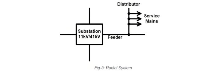
Radial System
In a radial system, separate feeders deliver power from a substation to each area, with power flowing unidirectionally from feeder to distributor. This design is simple and easy to implement, requiring lower initial investment compared to other systems.
However, its reliability is significantly limited: a failure in one feeder can shut down the entire system it serves. Voltage regulation also suffers for consumers far from the feeder, as load fluctuations cause more pronounced voltage variations. For these reasons, radial systems are typically used only for short-distance distribution to loads located near the feeder. A single-line diagram of the radial system is shown below.
Ring Main System
In a ring main system, distribution transformers are connected in a closed-loop configuration, supplied by a substation from one end. This design ensures each transformer has two distinct pathways to the substation, enhancing redundancy and reliability. A single-line diagram of the ring main system is illustrated below.
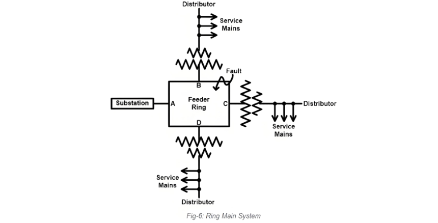
This configuration can be likened to two parallel-connected feeders. For instance, if a fault occurs between points B and C, the segment between B and C will be isolated from the system, and the substation can supply power through two alternative routes.
This design enhances system reliability, reduces voltage fluctuations at the consumer end, and ensures each loop segment carries a lower current—thus requiring less conductor material compared to the radial system.
Interconnected Distribution System
The interconnected distribution system features a loop supplied by multiple substations at different points, earning it the name "grid distribution system." A single-line diagram of this system is illustrated below.
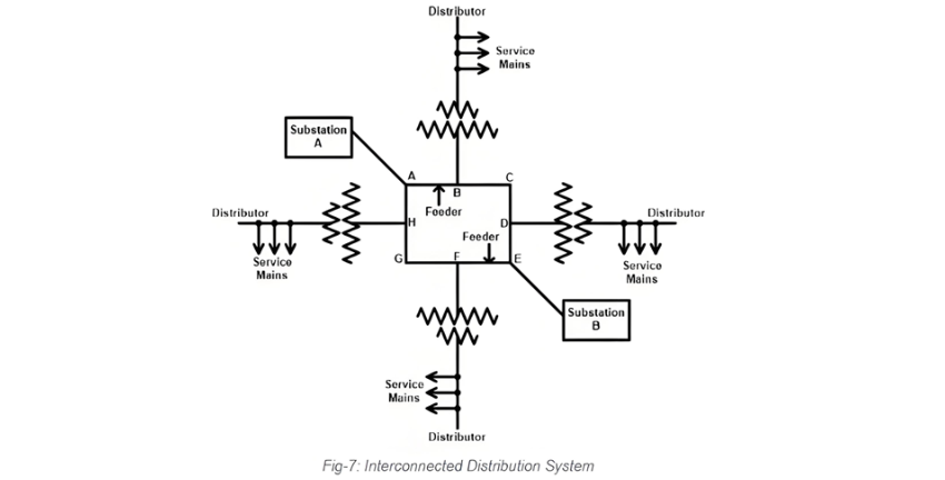
As depicted in the diagram above, the loop ABCDEFGHA is supplied by two substations at points A and E. This configuration significantly enhances system reliability compared to both ring main and radial systems.
While the interconnected system boasts superior power quality and efficiency—even reducing reserve power capacity—its design is complex and requires a higher initial investment due to the need for multiple substations.
Classification of Distribution Systems by Construction Type
Underground Distribution System
As the name implies, this system places conductors beneath streets or sidewalks. While safer than overhead systems, it incurs high initial costs due to trenching, conduits, manholes, and specialized cables. Underground cables are less prone to faults and offer aesthetic benefits (invisibility), but fault detection and repair are difficult. Their lifespan exceeds 50 years.
Overhead Distribution System
Conductors are mounted on wooden, concrete, or steel poles in this conventional setup. Though more susceptible to faults and safety hazards than underground systems, it has lower initial costs and greater flexibility for load expansion. Air serves as the insulation medium, eliminating the need for special cables and allowing higher current-carrying capacity. Installation, fault location, and repair are straightforward, keeping maintenance costs low—though it may interfere with communication systems. Its useful life spans over 25 years.