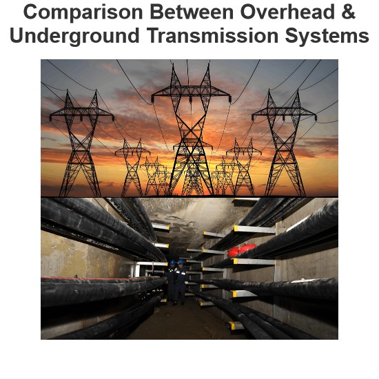
Current Limiting Reactor
A current limiting reactor is an inductive coil characterized by a significantly higher inductive reactance compared to its resistance, designed to restrict short-circuit currents during fault conditions. These reactors also mitigate voltage disturbances in the remainder of the power system. They are installed in feeders, tie lines, generator leads, and between bus sections to reduce the magnitude of short-circuit currents and alleviate associated voltage fluctuations.
Under normal operating conditions, current reactors allow unimpeded power flow. However, during a fault, the reactor restricts disturbances to the faulty section. Since the system's resistance is negligible compared to its reactance, the reactor's presence has minimal impact on overall system efficiency.
Main Function of Current Limiting Reactor
The primary objective of a current limiting reactor is to maintain its reactance when large short-circuit currents flow through its windings. When fault currents exceed approximately three times the rated full-load current, iron-cored reactors with large cross-sectional areas are used to limit fault currents. However, their high cost and weight due to bulky iron cores make air-cored reactors the preferred choice for short-circuit current limitation in most applications.
- Iron-Cored Reactors: Prone to hysteresis and eddy current losses, leading to higher power consumption.
- Air-Cored Reactors: Exhibit total losses typically around 5% of their KVA rating, making them more efficient.
Functions of Current Limiting Reactor
- Fault Current Protection: Reduces short-circuit current flow to safeguard equipment from mechanical stress and overheating.
- Voltage Disturbance Mitigation: Dampens voltage fluctuations caused by short circuits.
- Fault Isolation: Restricts fault currents to the affected section, preventing spread to healthy feeders and maintaining supply continuity.
Drawbacks of Current Limiting Reactor
- Increases the total percentage reactance of the circuit when integrated into the network.
- Degrades power factor and exacerbates voltage regulation issues.
Location of Reactors in Power Systems
Reactors are strategically placed in series with generators, feeders, or bus bars to limit short-circuit currents:
- Generator Reactors: Installed between generators and generator buses to provide individual machine protection, typically with a reactance of ~0.05 per unit.
- Drawback: A fault in one feeder can impact the entire system due to shared reactor configuration.
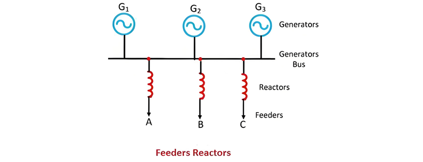
Disadvantages of Such Reactors
The drawbacks of this type of reactor are twofold: it fails to protect generators against short-circuit faults occurring across bus bars, and it causes constant voltage drops and power losses during normal operation.
Bus-Bar Reactors
When reactors are installed in bus bars, they are termed bus-bar reactors. Inserting reactors into bus bars helps avoid constant voltage drops and power losses. Below is an explanation of bus-bar reactors in ring systems and tie systems:
Bus-Bar Reactors (Ring System)
Bus-bar reactors serve to connect separate bus sections, which consist of generators and feeders linked to a common bus bar. In this configuration, each feeder is typically supplied by a single generator. Under normal operation, only a small amount of power flows through the reactors, resulting in low voltage drops and power losses. To minimize voltage drops across them, bus-bar reactors are therefore designed with high ohmic resistance.
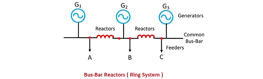
When a fault occurs in any feeder, only one generator supplies the fault current, while the current from other generators is limited by the bus-bar reactors. This reduces heavy current and voltage disturbances caused by short circuits on a bus section, confining them to the faulty section alone. The only drawback of this reactor configuration is its inability to protect generators connected to the faulted section.
Bus-Bar Reactors (Tie-Bus System)
This represents a modification of the above system. In a tie-bus configuration, generators are connected to the common bus bar via reactors, with feeders supplied from the generator side.
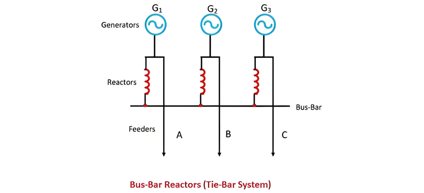
The system operates similarly to the ring system but offers additional advantages. In this configuration, if the number of sections increases, the fault current will not exceed a specific value, which is determined by the specifications of individual reactors.