What is Dual Trace Oscilloscope?
Dual Trace Oscilloscope
Definition: In a dual - trace oscilloscope, a single electron beam generates two traces, which are deflected by two independent sources. To produce these two separate traces, two main methods are employed: the alternate mode and the chopped mode. These are also referred to as the two operating modes of the switch.
A question then arises: why is such an oscilloscope necessary?
When analyzing or studying multiple electronic circuits, comparing their voltages is crucial. One option to make such comparisons is to use multiple oscilloscopes. However, synchronously triggering the sweep of each oscilloscope is a challenging task.
This is where the dual - trace oscilloscope comes in handy. It uses a single electron beam to provide two traces.
Block Diagram and Working of Dual Trace Oscilloscope
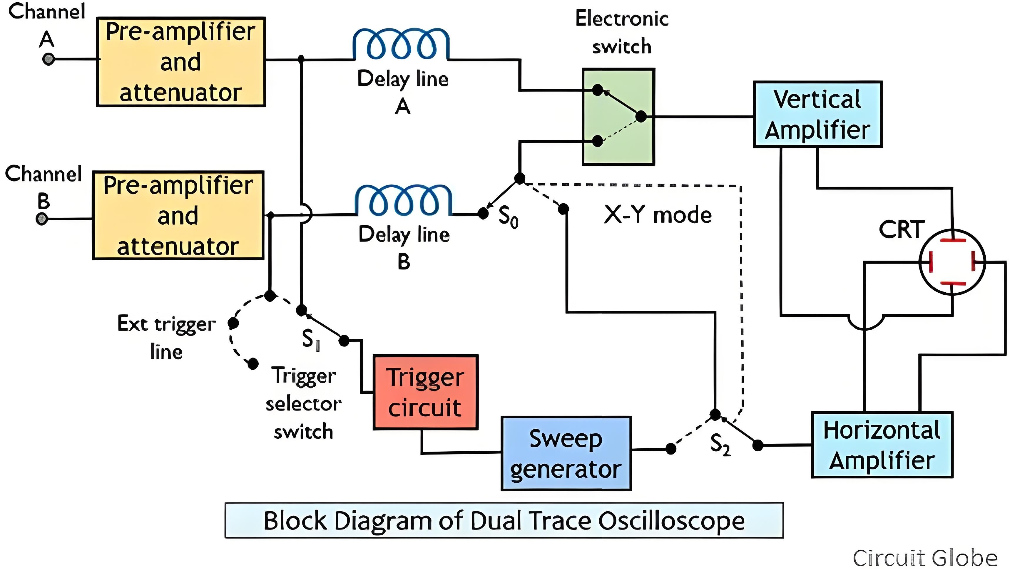
The figure below depicts the block diagram of a dual - trace oscilloscope:
Working Principle of Dual - Trace Oscilloscope
As can be seen from the above figure, the dual - trace oscilloscope has two independent vertical input channels, namely Channel A and Channel B.
The two input signals enter the pre - amplifier and attenuator stages separately. The outputs of these two independent pre - amplifier and attenuator stages are then sent to the electronic switch. This electronic switch transmits the input signal of only a single channel to the vertical amplifier at a specific moment.
The circuit is also equipped with a trigger selection switch, which allows the circuit to be triggered by the input of Channel A, the input of Channel B, or an externally applied signal.
The signal from the horizontal amplifier can be input to the electronic switch via the sweep generator or from Channel B through switches S0 and S2.
In this way, the vertical signal from Channel A and the horizontal signal from Channel B are provided to the Cathode - Ray Tube (CRT) to enable the operation of the oscilloscope. This is the X - Y mode of the oscilloscope, which enables accurate X - Y measurements.
In fact, the operation mode of the oscilloscope depends on the control selection of the front panel. For example, whether the waveform of Channel A is required, the waveform of Channel B is required, or the waveforms of Channel A or B are required separately.
As we have previously discussed, there are two operation modes for the dual - trace oscilloscope. Next, we will take a detailed look at these two modes respectively.
Alternate Mode of Dual - Trace Oscilloscope
When we activate the alternate mode, it allows the two channels to be connected alternately. This alternation or switching between Channel A and Channel B occurs at the start of each upcoming sweep.
In addition, there is a synchronization relationship between the switching rate and the sweep rate. This enables the waveform of each channel to be displayed in one sweep. For example, the waveform of Channel A will be displayed in the first sweep, and in the next sweep, the Cathode - Ray Tube (CRT) will display the waveform of Channel B.
In this way, the alternate connection of the two - channel input to the vertical amplifier is achieved.
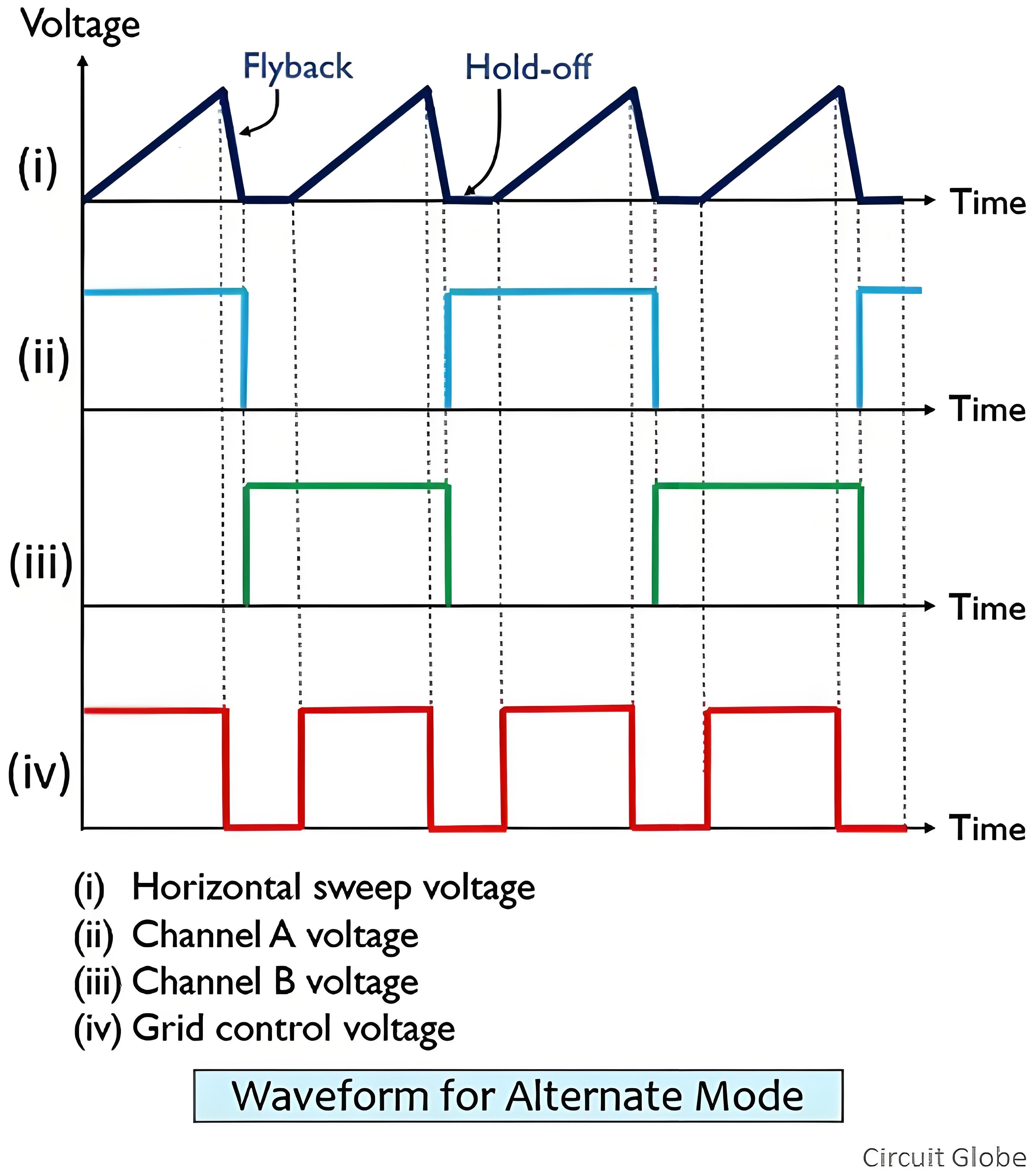
The electronic switch switches from one channel to another during the fly - back period. During the fly - back period, the electron beam is invisible, so the channel - to - channel switch can take place.
Therefore, a complete sweep will display the signal from one vertical channel on the screen, and in the next sweep, the signal from the other vertical channel will be displayed.
The following figure shows the output waveform of the oscilloscope operating in the alternate mode:
Working Principle of the Dual - Trace Oscilloscope
As is evident from the above diagram, the dual - trace oscilloscope is equipped with two independent vertical input channels, namely Channel A and Channel B.
The two input signals are fed into the pre - amplifier and attenuator stages respectively. The outputs of these two separate pre - amplifier and attenuator stages are then sent to the electronic switch. This electronic switch transmits the input signal of only one single channel to the vertical amplifier at a specific instant.
The circuit also features a trigger selection switch, which enables the circuit to be triggered by the input of Channel A, the input of Channel B, or an externally applied signal.
The signal from the horizontal amplifier can be fed into the electronic switch either via the sweep generator or from Channel B through switches S0 and S2.
In this manner, the vertical signal from Channel A and the horizontal signal from Channel B are supplied to the Cathode - Ray Tube (CRT) to enable the operation of the oscilloscope. This is the X - Y mode of the oscilloscope, which allows for precise X - Y measurements.
In reality, the operation mode of the oscilloscope depends on the control options on the front panel. For instance, whether the waveform of Channel A is needed, the waveform of Channel B is needed, or the waveforms of Channel A or B are required separately.
As previously mentioned, there are two operation modes for the dual - trace oscilloscope. Next, we will delve into these two modes respectively.
Alternate Mode of the Dual - Trace Oscilloscope
When the alternate mode is activated, it allows the two channels to be connected alternately. This alternation or switching between Channel A and Channel B occurs at the beginning of each scan.
Furthermore, there is a synchronization relationship between the switching rate and the scan rate. This enables the waveform of each channel to be presented during a single scan. For example, the waveform of Channel A will be displayed in the first scan, and in the next scan, the Cathode - Ray Tube (CRT) will display the waveform of Channel B.
In this way, the alternate connection between the two - channel input and the vertical amplifier is realized.
The electronic switch switches from one channel to the other during the flyback period. During the flyback period, the electron beam is invisible, thus allowing the channel switching to take place.
Therefore, a complete scan will display the signal from one vertical channel on the screen, and the next scan will display the signal from the other vertical channel.
The following diagram shows the output waveform of the oscilloscope when operating in the alternate mode:
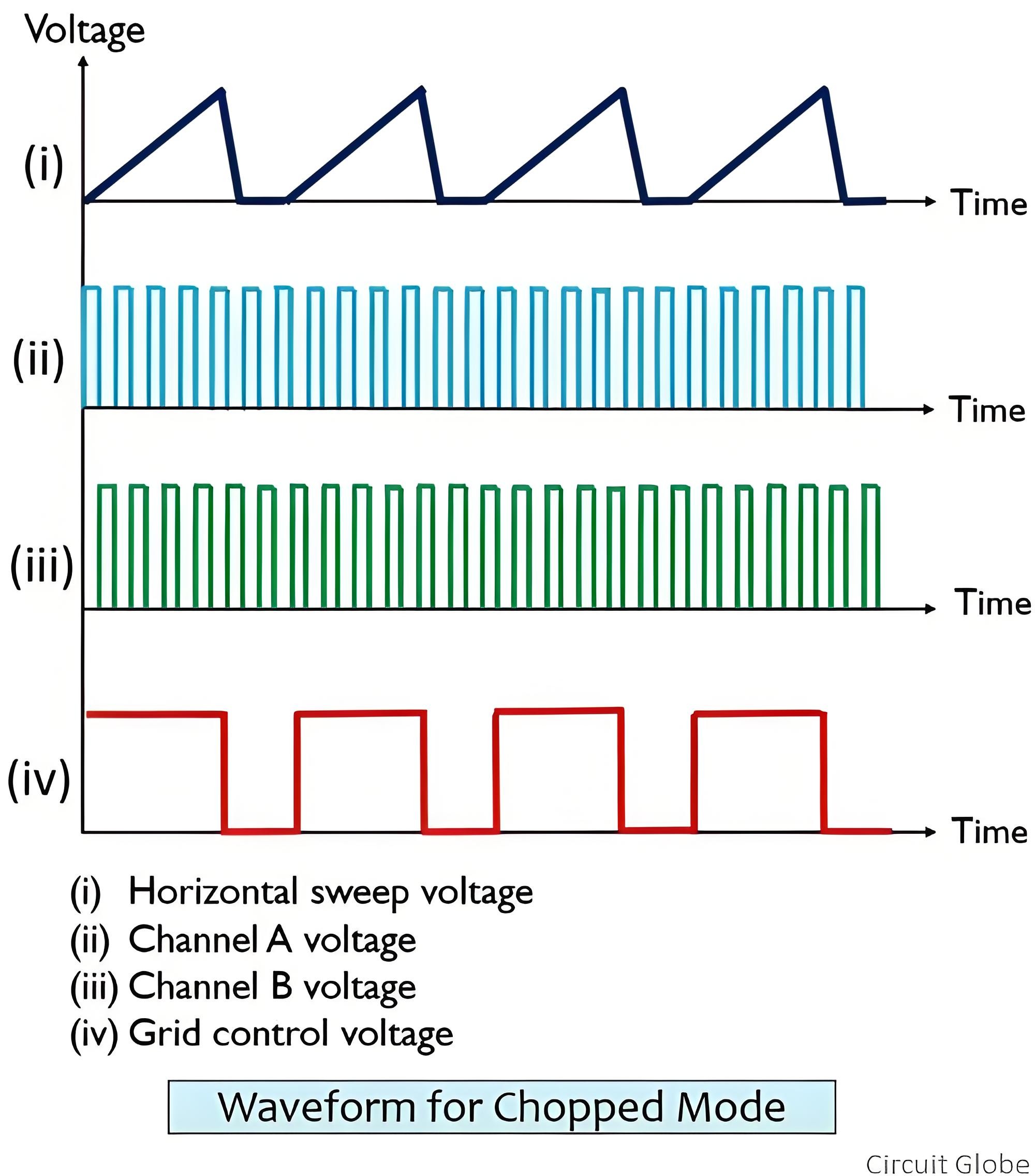
In this mode, the electronic switch operates freely at an extremely high frequency ranging from approximately 100 kHz to 500 kHz. Moreover, the frequency of the electronic switch is independent of that of the sweep generator.
Consequently, in this way, small segments of the two channels can be continuously connected to the amplifier.
When the chopping rate is higher than the horizontal sweep rate, the separately chopped segments will be merged and recombined to form the originally applied waveforms of Channel A and Channel B on the screen of the Cathode - Ray Tube (CRT).
However, if the chopping rate is lower than the sweep rate, it will surely lead to discontinuity in the display. Therefore, in such a case, the alternate mode is more appropriate.
The dual - trace oscilloscope allows for the selection of respective operation modes through the front panel of the instrument.
The Electricity Encyclopedia is dedicated to accelerating the dissemination and application of electricity knowledge and adding impetus to the development and innovation of the electricity industry.

