Solar Lantern

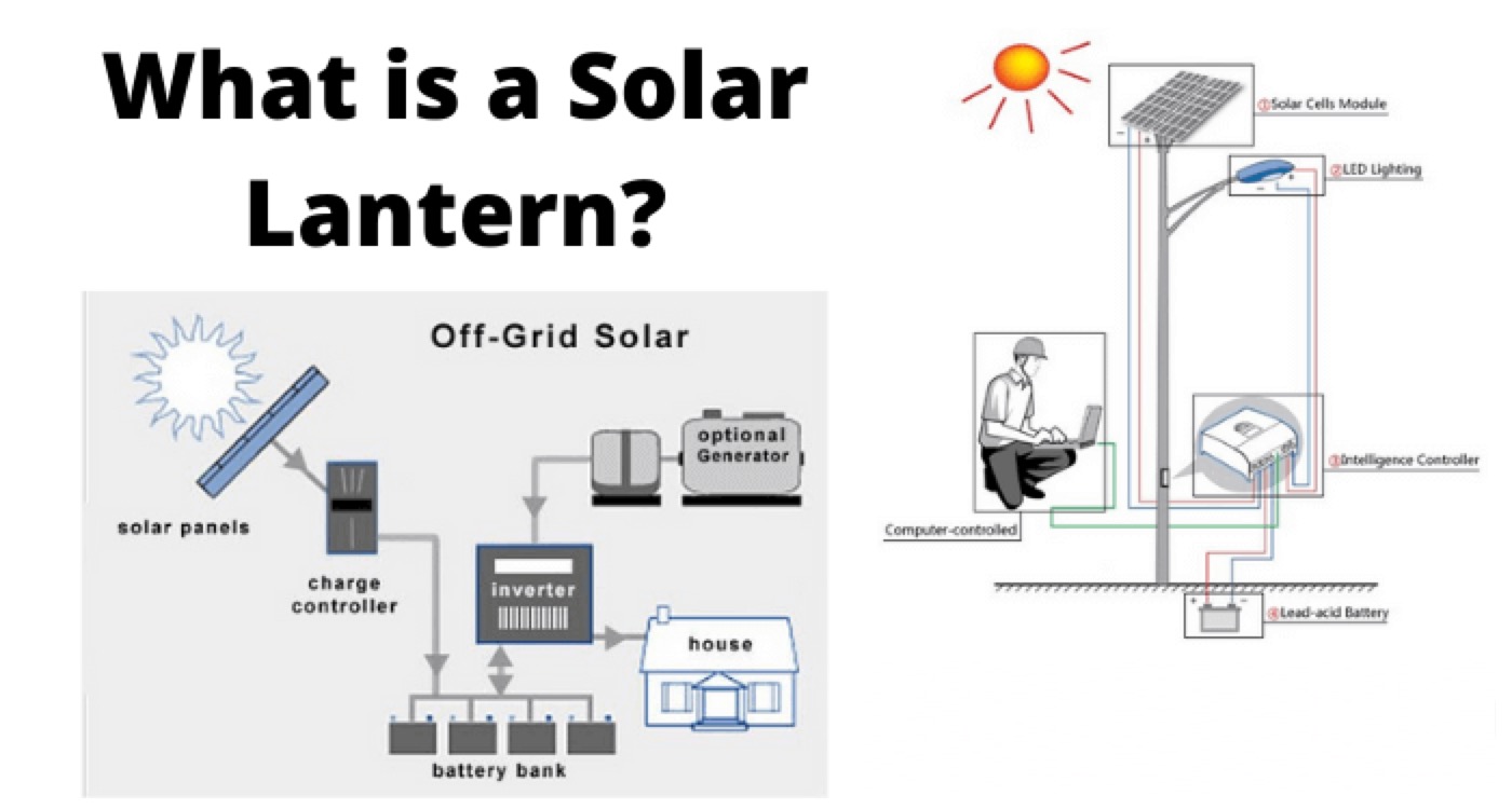
A solar lantern is well-known example portable stand-alone solar electric system. It consists of all necessary components required for a standalone solar electric system in a single casing except the solar PV module. It consists mainly an electric lamp, a battery and an electronic control circuit in a single casing. The solar PV module is the separated part of the lantern. We have to connect the solar PV module to the battery terminals of solar lantern for charging purpose. Nowadays, we use solar lanterns both for indoor and outdoor temporary lighting purposes. The casing of a solar lantern may be made of either metal, plastic or fibreglass. We place the battery, battery charging circuit and control circuit inside the casing in a proper manner. On the top of the casing, there is a lamp holder mounted at centre. We attach a fluorescent lamp (CFL) or LED lamp of the required rating to the holder. We cover the lamp from all sides with transparent fibreglass. On top of the transparent hollow cylindrical lamp cover, there is a top cover made of the same material by which casing of solar lantern is made. We fit a hanger to the top cover. There are a plug point, charging indication, discharging (ON) indication on the casing.
We connect the solar PV module placed under sunlight to the plug point on the casing for changing purpose, There are different models of solar lantern, but normally battery capacity of a solar lantern is 12 V 7 Ah. The CFL lamp used in this system is normally of either 5W or 7W. The solar PV module used for charging solar lantern ranges from 8 Watts peak to 14 Watts peak.
A table showing different configuration of solar lantern as per MNRE specifications is given below
Model |
Lamp (CFL) |
Battery |
PV Module |
I-A |
5 W |
12 V, 7 Ah at 20oC |
8 to 99 Watts (Peak) |
I-B |
5 W |
12 V, 7 Ah at 20oC |
8 to 99 Watts (Peak) |
II-A |
7 W |
12 V, 7 Ah at 20oC |
8 to 99 Watts (Peak) |
II-B |
7 W |
12 V, 7 Ah at 20oC |
8 to 99 Watts (Peak) |
The lumen output is generally in the range of 230 ± 5 % for 7 W CFL.
The Components of Solar Lantern
Solar Module or PV Module
Generally, the solar PV module used for charging a single solar lantern has rating of 8, 10 or 12 Watts peak (Wp). We normally keep the module on the rooftop at most tilt angle for which the module gets the maximum intensity of sunlight, for maximum duration. We connect the lanterns kept in room or other places to the solar PV module through wire socket. Sometimes users do not install the solar module on the rooftop instead they like to keep a portable module in sunlight on a daily basis.
Battery
Normally we use maintenance free sealed dry type lead acid battery of tabular shaped with 12 V, 7 Ah capacity for solar lantern.
Inverter
For CFL lamp one inverter is required to make the battery output of AC. The inverter should have at least 80% efficiency.
Protection and Indication System
The lantern has an electronic circuit to provide cut off provision to prevent excessive charging or over discharging of the battery. We also provide an electrical fuse with the system to protect it from any short circuit fault. In addition to these we provide two Light Emitting Diodes (LEDs) on the casing for indiating charging and deep discharging states of the solar lantern.
LED Based Solar Lantern
Solar electricity is expensive. The availability of solar electricity in a portable solar module is small. So, LED has become most suitable light source in portable handy solar lantern. The LED is best suited for small household lantern because of its small electricity consumption. Although LEDs are manufactured in different colours, white colour LED is most suitable for a solar lantern. As the electricity consumption rate of LEDs is quite low, the power ratings of the PV module used to charge the lantern is also low and if the peak power rating of a solar module is more than 2.5 W at 17 V it can be suitably used to charge a LED-based solar lantern. Became of low power consumption, the battery of this lantern is also smaller and of a lower rating. A 2.3 Ah 12 V at 20 oC sealed, maintenance-free dry type lead acid battery can be suitably used for LED solar lantern. More than 30 lumens per Watt 5 mm white LED is most suitable for a LED-based solar lantern.
Statement: Respect the original, good articles worth sharing, if there is infringement please contact delete.
Electrical4U is dedicated to the teaching and sharing of all things related to electrical and electronics engineering.


