IEC61850 model for GIS with Non Conventional Instrument Transformers (NCIT)

Edwiin
05/06/2025
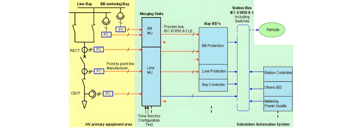
IEC 61850 Standards and NCIT - Related Communication in GIS
The IEC 61850 8 - 1 standard is specifically applicable to station bus communication, providing a framework for data exchange and interoperability within substation automation systems. On the other hand, the IEC 61850 9 - 2 LE standard is directly relevant to the communication of Non - Contact Inductive Transducer (NCIT) sensors.
Ethernet optical communication drivers play a crucial role in this setup. Their significance stems from the utilization of glass core fiber optics as the physical transmission medium. Fiber optics offer advantages such as high - speed data transfer, immunity to electromagnetic interference, and long - distance communication capabilities, making these drivers essential for reliable and efficient communication.
Due to the inherently low - level output signals from an NCIT metering element, the presence of a "Primary Converter" (PC) in close proximity is indispensable. The PC is an electronic device equipped with several key functions. It incorporates signal filtering through a low - pass filter to eliminate unwanted high - frequency noise, digitizes the signal using a Controller Area Network (CAN) interface, and performs necessary signal processing. These operations ensure that the raw signals from the NCIT are in a suitable form for further transmission and analysis.
The computational capabilities of the PC are harnessed to communicate with a device known as the Merging Unit (MU) via a proprietary protocol. The MU serves as a central hub, aggregating inputs from multiple PCs. It is equipped with multiple output ports, which are designed to enable communication with various pieces of equipment, including protection relays, bay controllers, and metering devices. By distributing the processed measurements to these different systems, the MU facilitates seamless integration and coordinated operation within the overall electrical infrastructure.
To achieve optimal metering accuracy, it is imperative to match the sensitivity level of the metering element with the background noise level of the printed circuit board. Minimizing the background noise to the lowest possible level ensures that the metering element can accurately detect and measure electrical quantities without being affected by spurious signals.
Figure [1] illustrates the IEC 61850 communication protocol in conjunction with NCIT sensors for Gas Insulated Substations (GIS). This visual representation provides a comprehensive overview of how the various components interact and communicate, highlighting the integration of standards - based communication and specialized sensor technology to enhance the performance, reliability, and efficiency of GIS - based electrical systems.
Edwiin

Classification of Electric Power Distribution Network Systems
The typical electric power system network is categorized into three main components: generation, transmission, and distribution. Electric power is produced in power plants, which are often located far from load centers. As a result, transmission lines are employed to deliver power over long distances.To minimize transmission losses, high-voltage power is used in transmission lines, and the voltage is reduced at the load center. The distribution system then delivers this power to end-users.Types
Edwiin
06/05/2025
Why is the Ground Wire Always Positioned Above the Overhead Power Lines?
Ground Wire in Overhead Transmission LinesThe ground wire (also called earth wire or OPGW) installed above phase lines in overhead transmission lines acts as a key protective and safety component. It provides lightning protection, ground fault defense, and helps prevent electrical system disruptions.In overhead transmission lines, positioning the ground wire above phase lines serves specific safety and performance purposes. Referred to as a "shield wire" or "static wire," this configuration has
Edwiin
06/04/2025
What is the Power Angle in a Power Transmission Line?
The power angle, denoted by δ, is the phase angle difference between two voltage levels in a power transmission line. Specifically, it represents the angular discrepancy between the sending-end voltage phasor and the receiving-end voltage (or between voltages at two bus points). In simpler terms, it quantifies the phase shift between voltage and current waveforms in the transmission line.Also referred to as the torque angle or load angle, this parameter is critical for two key reasons: it
Edwiin
06/04/2025
Permanent Magnet Moving Coil or PMMC Instrument
DefinitionInstruments that utilize a permanent magnet to generate a stationary magnetic field within which a coil moves are known as Permanent Magnet Moving Coil (PMMC) instruments. They operate on the principle that torque is exerted on a moving coil situated in the magnetic field of a permanent magnet. PMMC instruments provide accurate results for direct current (DC) measurements.Construction of PMMC InstrumentThe moving coil and the permanent magnet are the key components of a PMMC instrument
Edwiin
05/30/2025
Inquiry
Download
Experts Electrical is dedicated to serving the personnel in the global power industry.
Join Experts Electrical, not only can you discover power equipment and power knowledge, but also canhnd like - minded friends!