Vacuum arcs differ significantly from the gas arc discharge phenomena we previously studied. Gas ionization is not the main factor contributing to arc generation. Instead, vacuum arc discharge forms in the metallic vapor emitted from the contact electrodes. Moreover, the characteristics of the arc vary depending on the magnitude of the interrupting current. Generally, we categorize them into low - current vacuum arcs and high - current vacuum arcs.
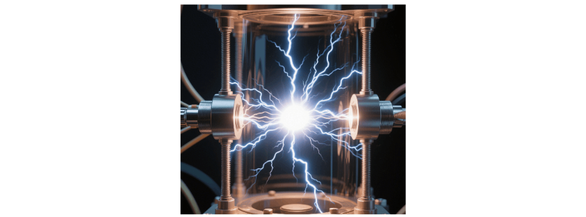
Low - current Vacuum Arc: When the contacts break in a vacuum, highly concentrated cathode spots with current and energy are generated. A large amount of metallic vapor evaporates from these cathode spots, where the density of metal atoms and charged particles is very high, and the arc burns within this environment. Meanwhile, the metallic vapor and charged particles in the arc column continuously diffuse outward, and the electrodes keep evaporating new particles to replenish. When the current passes through zero, the arc's energy decreases, the electrode temperature drops, the evaporation effect lessens, the particle density in the arc column reduces, and finally, the cathode spots disappear when passing through zero, leading to arc extinction. Sometimes, if the evaporation effect cannot maintain the diffusion rate of the arc column, the arc extinguishes suddenly, resulting in current chopping.
High - current Vacuum Arc: When breaking a large current, the energy of the vacuum arc increases, and the anode also heats up severely, forming a strong constricted arc column. At the same time, the effect of electrodynamic force becomes more pronounced. Therefore, for high - current vacuum arcs, the magnetic field distribution between the contacts has a decisive influence on the arc's stability and arc - extinguishing performance. If the current is too large, exceeding the limiting interrupting current, interruption failure will occur. At this point, the contacts heat up severely, continue to evaporate even after the current passes through zero, and it is difficult for the dielectric to recover, making it impossible to interrupt the current.
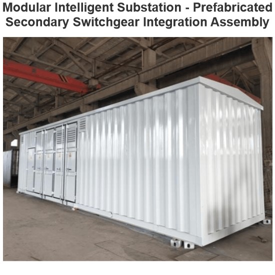
Taking zw27-12 as an example, the following elaborates on its structure and working principle.
The main body of the circuit breaker consists of the conductive circuit, insulation system, seals, and the housing. It has a three - phase common - box structure. The conductive circuit is composed of incoming and outgoing conductive rods, incoming and outgoing insulation supports, conductive clamps, flexible connections, and a vacuum arc - extinguishing chamber. This mechanism features electric energy storage and electric opening and closing, while also having a manual operation function. The entire structure is made up of components such as the closing spring, energy - storage system, over - current trip device, opening and closing coils, manual opening and closing system, auxiliary switch, and energy - storage indicator.
A vacuum circuit breaker utilizes the phenomenon that when the current in a high - vacuum environment passes through zero, the plasma diffuses rapidly, thereby extinguishing the arc and achieving the goal of cutting off the current.
The measurement of the opening distance and over - travel of a circuit breaker: The difference in the measured x - values when the circuit breaker is in the open and closed states is the opening distance of the circuit breaker, and the difference in the measured y - values is the over - travel of the circuit breaker. The adjustment is achieved by lengthening or shortening the insulating operating rod or the connecting rod between the mechanism and the main shaft.
- The engagement amount between the rocking arm and the half - shaft should be 1.5 - 2.5mm, which can be adjusted by screws.
- When the transmission sleeve rotates to the maximum angle, there should be a 1.5 - 2mm gap between the rocking arm and the half - shaft. This ensures that when the transmission sleeve returns to the closing position, the rocking arm can automatically latch onto the half - shaft, and this can be achieved through screw adjustment.
- The conversion of the auxiliary switch should be accurate and reliable, which can be realized by adjusting the position of the toggle arm of the auxiliary switch and the length of the lever.
- During the energy - storage process, when the ratchet reaches the highest point of the last tooth, it should ensure that the toggle arm on the energy - storage sleeve can reliably switch the contacts of the travel switch to cut off the power supply of the motor. This can be achieved by adjusting the up - down, front - back position of the travel switch.
- Adjust the pre - stretching length of the opening and closing springs to ensure the reliable opening and closing of the circuit breaker and that the opening and closing speed reaches the specified value.
In most 35kV standardized substations in rural power grids, the principle of separating the control busbar from the closing busbar is adopted. Due to frequent lightning, rain, and strong wind in mountainous areas, which lead to multiple trippings and an increased number of switch closing operations, the closing coils of switches are extremely prone to burnout. Here, I suggest making a minor improvement to the control circuit.
Insert a pair of normally - open contacts of the circuit breaker's energy - storage travel switch in series between the auxiliary normally - closed contacts of the circuit breaker and the closing coil. In this way, when the circuit breaker is not energized (not energy - stored), the closing operation cannot be carried out. This prevents closing when the circuit breaker is not energized, thus avoiding the situation where the closing circuit remains on and burns out the closing coil.
Meanwhile, during the wiring process, it is necessary to ensure that the polarities of the closing busbar and the control busbar at the contacts of the energy - storage travel switch are consistent. This is to prevent the arcing in the closing circuit from puncturing the travel switch when the switch is being energized, which could cause the control fuse to blow or the control air switch to trip. This point requires special attention in integrated automated substations.
Vacuum circuit breakers have a short arcing time, high insulation strength, and a relatively long electrical life. With small contact opening distances and over - travel, and minimal operating energy, they also enjoy a long mechanical life. During daily operation, maintenance tasks are relatively few. Mainly, it is necessary to check for wear on the moving parts of the mechanism, ensure that fasteners are not loose, clean the dust off the insulation surface, and apply some lubricating grease to the moving parts.
During preventive tests, the DC resistance test results of the switch should be compared with historical data. If any issues are identified, timely replacement or rectification is required. The power - frequency withstand voltage test for the breaker is an effective method to check for leakage in the vacuum interrupter. (For indoor vacuum circuit breakers, the color of the flash inside the vacuum interrupter when the load is disconnected can be used to preliminarily assess the vacuum level. A dark red color indicates a reduced vacuum level, while a light blue color indicates a good vacuum level.)
During protection setting verification, a low - voltage closing test is conducted on the circuit breaker to verify whether the switch operates reliably when the busbar is in a fault state and the voltage drops.