Stator Voltage Control of an Induction Motor

Edwiin
05/23/2025

Stator voltage control represents a method employed to regulate the speed of an induction motor. The rotational speed of a three-phase induction motor can be adjusted by varying the supply voltage. As is well established, the torque generated by the motor is proportional to the square of the supply voltage, while the slip at the point of maximum torque remains independent of the supply voltage. Notably, fluctuations in the supply voltage do not affect the synchronous speed of the motor.
The torque-speed characteristics of three-phase induction motors under different supply voltages, along with the characteristics for a fan load, are illustrated below:
Stator voltage control is a technique used to regulate the speed of an induction motor. The rotational speed of a three-phase induction motor can be adjusted by varying the supply voltage. The torque generated by the motor is proportional to the square of the supply voltage, while the current is directly proportional to the voltage. Thus, the speed is controlled by adjusting the voltage until the motor develops the torque required by the load at the desired speed.
To reduce the speed while maintaining the same current, the voltage is decreased, which in turn reduces the torque output. This stator voltage control method is particularly suitable for applications where the load torque decreases with speed, such as fan loads.
This approach allows speed control only below the normal rated speed, as operating at voltages higher than the rated value is not permissible. It is ideal for drives requiring intermittent operation, as well as fan and pump systems, where the load torque varies with the square of the speed. These drives demand lower torque at lower speeds, a condition that can be met by applying a lower voltage without exceeding the motor's current rating.
For speed control of small-sized motors (primarily single-phase), variable voltage can be achieved through the following methods:
  • Connecting an external resistance in the motor's stator circuit.
  • Using an auto-transformer.
  • Employing a thyristor voltage controller.
  • Utilizing a triac controller.
The thyristor voltage controller method is now the preferred choice for voltage variation. For a single-phase supply, two thyristors are connected back-to-back, as illustrated in the figure below:
The domestic fan motors, which are single-phase are controlled by a single-phase Triac Voltage Controller as shown in the figure below:
Speed control is achieved by adjusting the firing angle of the Triac. These controllers are commonly referred to as solid-state fan regulators. Compared to conventional variable regulators, solid-state regulators offer greater compactness and efficiency, making them the preferred choice over traditional regulators.
For a three-phase induction motor, three pairs of thyristors are required, with each pair consisting of two thyristors connected back-to-back. The diagram below illustrates the stator voltage control of three-phase induction motors using a thyristor voltage controller:
Each pair of thyristors controls the voltage of the corresponding phase. Speed regulation is achieved by adjusting the conduction period of the thyristors. For lower power ratings, the back-to-back thyristor pairs in each phase can be replaced by a Triac.
Edwiin

Generator Protection – Types of Faults & Protection Devices
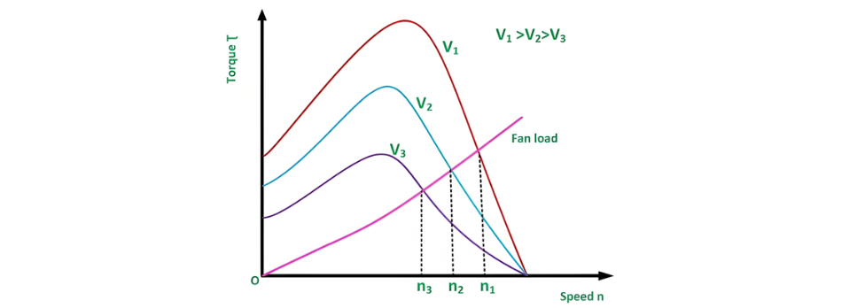
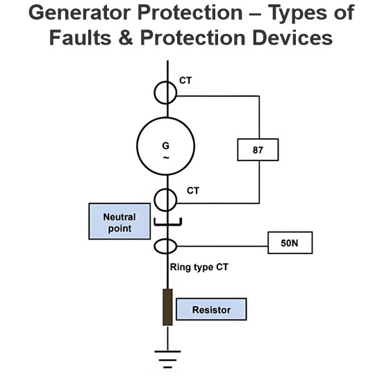
Common Generator Faults and Protection SystemsClassification of Generator FaultsGenerator faults are primarily categorized into internal and external types:Internal Faults: Arise from issues within generator components.External Faults: Stem from abnormal operating conditions or external network issues.Faults in prime movers (e.g., diesel engines, turbines) are mechanical in nature and defined during equipment design, though they must integrate with generator protections for tripping purposes.Typ
Edwiin
06/05/2025
Short Circuit Ratio of a Synchronous Machine
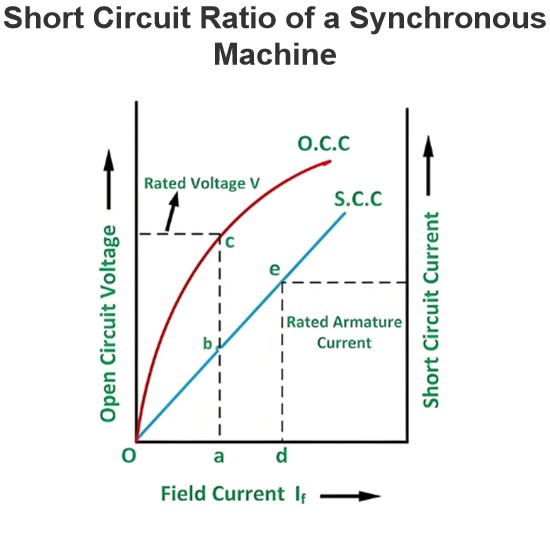
The Short Circuit Ratio (SCR) of a Synchronous MachineThe Short Circuit Ratio (SCR) of a synchronous machine is defined as the ratio of the field current needed to generate rated voltage under open-circuit conditions to the field current required to sustain rated armature current during a short-circuit condition. For a three-phase synchronous machine, the SCR can be derived from its Open-Circuit Characteristic (O.C.C) at rated speed and Short-Circuit Characteristic (S.C.C), as illustrated in the
Edwiin
06/04/2025
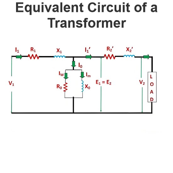
Equivalent Circuit of a Transformer
The equivalent circuit diagram of any device can be extremely useful for predicting how the device will behave under different operating conditions. It is essentially a circuit - based depiction of the equations that describe the device's performance.The simplified equivalent circuit of a transformer is constructed by representing all of the transformer's parameters on either the secondary side or the primary side. The equivalent circuit diagram of the transformer is presented below:Let the equi
Edwiin
06/03/2025
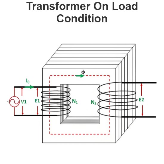
Transformer On Load Condition
Transformer Operation Under Load ConditionsWhen a transformer is under load, its secondary winding connects to a load, which can be resistive, inductive, or capacitive. A current I2 flows through the secondary winding, with its magnitude determined by the terminal voltageV2and load impedance. The phase angle between the secondary current and voltage depends on the load characteristics.Explanation of Transformer Load OperationThe operational behavior of a transformer under load is detailed as fol
Edwiin
06/03/2025
Inquiry
Download
Experts Electrical is dedicated to serving the personnel in the global power industry.
Join Experts Electrical, not only can you discover power equipment and power knowledge, but also canhnd like - minded friends!