What is included in the operational procedures of a smart electricity meter load switch?

James
06/28/2025

As a frontline operator who deals with smart electricity meters daily, I’m well - versed in the design and operational norms of load switches (both internal and external) in these meters. Below, I’ll break down the technical requirements and practical key points based on my on - site experience for easy reference.
I. Basic Understanding of Internal and External Load Switches
In the type specifications for single - phase and three - phase smart electricity meters (such as environmental conditions, specifications, display requirements for single - phase meters, all detailed in appendices), clear labeling rules are set for single - phase prepaid smart meters and three - phase remote prepaid smart meters (excluding three - phase smart meters and local prepaid meters). For meters with internal switches, it’s marked “Label when internal switch is used”; for those with external switches, “Label when external switch is used”. For us frontline workers, just checking the nameplate lets us quickly tell if the load switch is internal or external – super practical.
II. Selection and Technical Requirements for Internal/External Load Switches
(I) Selection Principles
When installing meters on - site, if I encounter an internal load switch, I always check that the maximum current generally doesn’t exceed 60A. For external ones, the trip output interface must strictly comply with Q/GDW 1354 - 2012. It’s a hard requirement; getting it wrong can cause problems.
(II) Technical Specifications
  • General Requirements: The load switch must meet the IEC 62055 - 31:2005 standard. Three - phase switches are best designed as an integrated unit for better stability. In the equipment I’ve handled, integrated ones indeed have a lower failure rate.
  • Special Requirements for Internal Switches: For meters with internal load switches, arc - quenching measures (either hardware or software) are needed during switch operations. The output circuit must prevent misoperation and be easy for on - site testing. Also, the switch must work normally during voltage fluctuations (within the extended operating voltage range). Once, the voltage on - site was unstable, but the internal switch held up and didn’t affect the user’s power supply – that’s how crucial this is.
  • Control Modes for External Switches
    • Mode 1 (Commonly Used): Passive and non - polar signals are output from the trip control terminals (Terminals 5 & 6 for single - phase; 13, 14, 15 for three - phase). The contact capacity is AC 250V/2A. In the non - excited state, it closes (allowing power use); in the excited state, it opens (cutting off power). This is the mainstream choice for manufacturers – simple and reliable. But we must ensure correct wiring to avoid mistakes.
    • Mode 2 (Less Used but Good to Know): An AC voltage control signal is output from Terminal 5 (Terminal 13 for three - phase), with a driving capability ≥20mA. In the non - excited state, the output is 90% - 100% of the supply voltage; in the excited state, 0% - 25%. However, this mode has risks – the terminals carry strong electricity, changing our usual operation habits. Also, the verification device needs modification (original auxiliary terminals only handle up to 40V). So it’s rarely used in practice, but we still need to be aware of it.

III. Supplementary Requirements and Practical Details for Load Switches
(I) Supplementary Design Requirements

  • When the voltage line fluctuates between 80% - 115% of the reference voltage, the switch control circuit must work normally. This is vital for power stability, especially in areas with unstable voltage.
  • If an external switch uses pulse control, it’s recommended to have redundant pulse width (e.g., 400ms) to prevent misjudgment. I once had a case where overly narrow pulses caused misoperation; adjusting to this requirement fixed it.
  • For the trip control signal of external switches, it’s recommended to uniformly draw AC signals from Phase A to avoid wiring confusion across regions and ensure consistency in inspection and supply.
  • During bidding tests, the control mode for external switches should preferably use pulse output, and the test terminals should be treated as below 40V. This unifies standards for easier inspection.
(II) Operational Norms
After a user purchases electricity, closing the circuit has two modes: Direct Closing and Permitted Closing, following communication commands in DL/T 645 - 2007. I deal with these commands daily, so I’ve mastered every scenario:
  • Trip Operation
    • Internal Switch Meters: Upon receiving a “Trip” command, they trip immediately. The “Power Off” character stays displayed, and the trip indicator light turns on – no delays allowed.
    • External Switch Meters: Similarly, they trip instantly without delay. The character display and indicator light status are the same as internal switch meters. On - site, when dealing with arrears - related trips, this step must be reliable.
  • Permitted Closing Operation
    • Internal Switch Meters: After receiving a “Permitted Closing” command, the “Power Off” character disappears, and the trip indicator light flashes (on for 1s, off for 1s). The user presses and holds the button for 3s to close the internal switch, and the light turns off. We need to teach users the correct operation to avoid mistakes.
    • External Switch Meters: After receiving the command, the internal relay closes directly. The character disappears, and the indicator light turns off. Users don’t need to press the meter button – just close the external switch, which is simpler.
  • Direct Closing Operation
    • Internal Switch Meters: Upon receiving the command, the internal switch closes directly, and the indicator light turns off.
    • External Switch Meters: Upon receiving the command, they close immediately.
Special Cases: For internal switch meters, a direct closing command triggers an automatic closure. For a permitted closing command:
  • Local prepaid meters (CPU card/RF card) require card insertion to close.
  • Remote prepaid meters need a 3 - second long press on the dial key to close.
For external switch meters, a permitted closing command triggers the internal relay to close directly – users only need to close the external switch.
Summary: External switches don’t require pressing the meter button for tripping/closing. For internal remote prepaid meters, when a permitted closing command is received, users must press the dial key for 3s – we need to clearly explain this to users to avoid misoperations.
IV. Notes on AC Voltage Testing
If an external switch uses the “AC voltage control signal” (Mode 2), the auxiliary terminals (for tripping and alarming) actually carry strong electricity, with the reference voltage exceeding 40V. During AC voltage testing, treat them as “auxiliary circuit terminals with reference voltage exceeding 40V”. This affects test safety and equipment lifespan – we frontline inspectors must never be careless here.
James

Professionalism builds strength. As an expert in the installation and operation of electrical equipment, I am proficient in the installation process and strictly adhere to standards. I skillfully master the operation essentials and can swiftly eliminate faults. With a heart that constantly explores new knowledge, I illuminate the path to the efficient operation of electrical equipment.

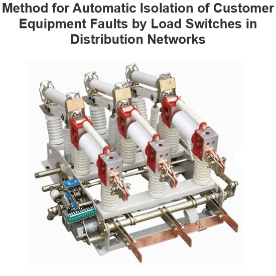
Method for Automatic Isolation of Customer Equipment Faults by Load Switches in Distribution Networks
1 OverviewDistribution network safety has long been under - addressed, with its automation lagging substation automation . Using 10 kV intervals of existing substations to set line section points meets future grid needs . Configuration of distribution switches, section switches, and protection must match substation outgoing - line protection for reliability. Fault isolation, self - healing, and restoration are key to distribution automation .Scholars have studied smart distribution network fault
Felix Spark
06/30/2025
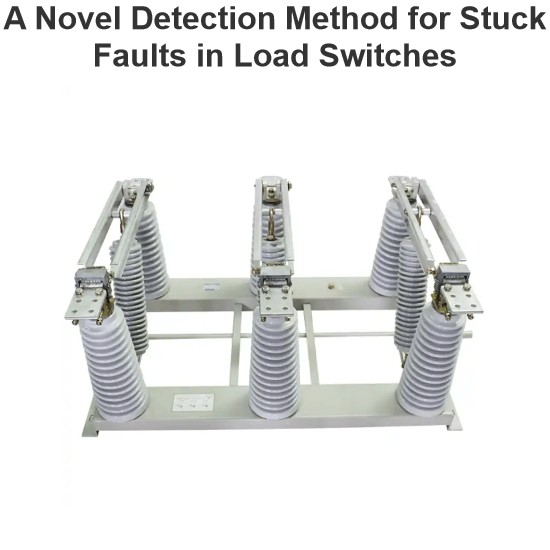
A Novel Detection Method for Stuck Faults in Load Switches
In recent years, as distribution automation advances, load switches see wider use in distribution lines. Yet, mechanical - failure - induced accidents are on the rise, burdening line operation and maintenance.Poor mechanical performance is the main cause of switch faults. Many scholars study large - scale switchgear operation, using methods like coil current detection, vibration signal analysis, switch travel testing, ultrasonic flaw detection, and infrared thermometry. Motor - current - based s
Oliver Watts
06/30/2025
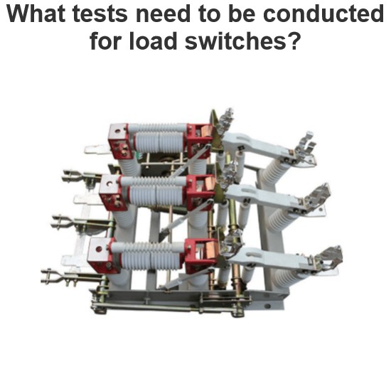
What tests need to be conducted for load switches?
As a technician with years of on-site experience in power testing, I understand the importance and complexity of load switch testing. Below, I combine practical work experience to elaborate on the full process of load switch testing, from testing items and methods to equipment and procedural specifications.I. Routine Electrical Performance Testing(1) Loop Resistance TestLoop resistance is a core indicator for evaluating a load switch's conductivity. I strictly follow GB/T 3804 and GB 1984 standa
Oliver Watts
06/28/2025
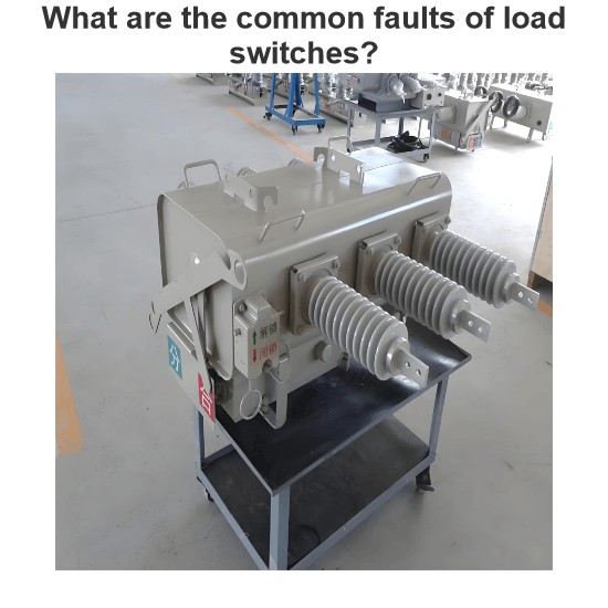
What are the common faults of load switches?
As an on-site maintenance technician, I frequently deal with electrical, mechanical, and insulation faults in load switches. The following outlines fault manifestations, causes, and solutions:I. Electrical Fault Handling(1) Contact HeatingContact heating is mainly caused by poor contact, insufficient pressure, or three-phase asynchrony. When the contact resistance exceeds 1.5 times the initial value, the temperature rise will exceed the standard in a 40℃ environment. For example, the FW4-10 swit
Felix Spark
06/28/2025
Inquiry
Download
Experts Electrical is dedicated to serving the personnel in the global power industry.
Join Experts Electrical, not only can you discover power equipment and power knowledge, but also canhnd like - minded friends!