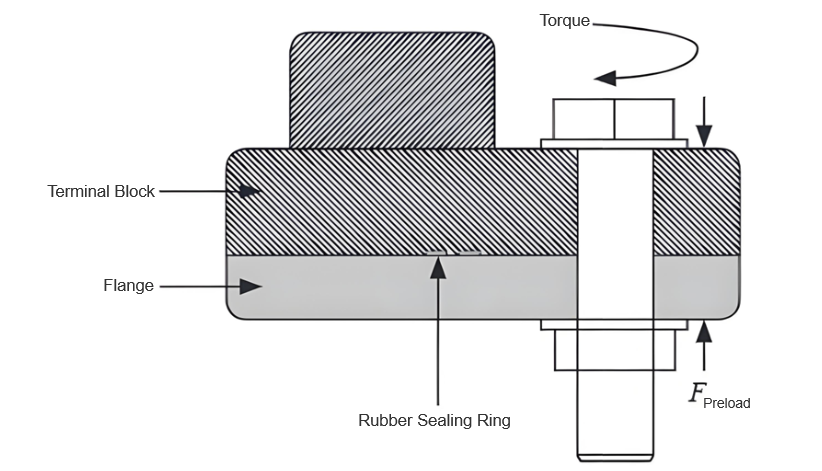
What are the possible causes of cracking failure in CT terminal blocks within GIS equipment?

Felix Spark
07/07/2025

Gas - insulated switchgear (GIS) , often called “SF6 combined electrical apparatus”, is widely used in power systems for its high reliability, small footprint, low noise, and low loss. It encloses high - voltage devices like circuit breakers, fast grounding switches, current transformers, and busbars in a grounded metal shell filled with SF6 gas . Each device sits in a separate gas chamber with different pressures. The CT terminal block divides gas chambers, connects components, and eases maintenance . A converter station found a 750kV GIS CT gas chamber’s pressure dropped ~0.05MPa daily, persisting after gas refilling. Thus, we analyzed the CT terminal block’s failure.
1 Overview and Cracking Analysis of the Terminal Block
1.1 Overview
Put into operation on 2017 - 06 - 23, the terminal block leaked gas on 2021 - 11 - 06 and showed cracks on 2021 - 11 - 08. The flat side is CT - side, convex is non - CT - side, with 12 outer threaded holes. CT - side has three circles of equidistant yellow copper terminal posts (1, 8, 15 per circle from inside); non - CT - side’s outermost circle has 15 posts (A1 - A5, B1 - B5, C1 - C5 counterclockwise), matching CT - side in middle circles.
1.2 Macroscopic Inspection
A ~30cm - long crack was found on the convex side, at the raised edge’s turn, split into two sections: a wide - opened long crack (A1 - B1) and a small - opened short crack (C5 - A1, barely visible). Penetrant testing followed to check for more cracks.

1.3 Penetrant Testing

Penetrant testing was conducted on both sides of the terminal block:

  • Convex side: Two cracks were found, consistent with macroscopic inspection in morphology and length (240mm and 60mm). The short crack became obvious after testing, and no other cracks were detected.
  • Flat side: Two cracks of different lengths (approximately 20mm and 8mm) were found at the inner sealing ring. They did not penetrate through, with an end - to - end distance of about 20mm.
1.4 Fracture Surface Inspection
A section cut from A4 showed non - CT - side penetrative cracks and CT - side non - penetrative ones. Square conductive sheets and hexagonal nuts inside had structural abrupt changes,with penetrant back - seepage (gaps between metal inserts and epoxy resin). Fine cracks (30° to the terminal block axis) and uneven, spotted contact surfaces (with 45° - angled cracks) were seen.
1.5 Force Calculation
With the manufacturer’s 25Nm bolt torque, using T = kFd ((k = 0.15), the single - bolt vertical preload was 13.9kN. Simulating max preload (M12 bolt, 50cm torque wrench) gave 220Nm torque (44Nm via a 10cm - arm wrench), raising preload to 24.4kN (1.76× standard). The 30° - angled, 31.78mm - long fracture had a 10.78mm discontinuous joint (resin stress increase). Excessive preload and stress concentration caused crack initiation and propagation in resin.
2 Causes of Cracking
Excessive bending stress on the discontinuous seat structure (edge bolt hole - terminal post) caused penetrative cracks. Improper tools/over - tightening led to excessive bolt preload. CT - side gas pressure
added to bending stress. Poor metal - resin bonding (gaps) reduced bearing cross - section and caused stress concentration. Combined, these cracked the terminal block, leaking gas.
3 Preventive Measures
Use torque wrenches per manufacturer specs to avoid over - tightening. Follow gas - filling processes to prevent pressure differences. Optimize terminal block design/casting to avoid stress - causing gaps/sharp inserts. Strengthen quality checks to reject faulty products.
4 Conclusion
CT terminal block cracking in SF6 apparatus resulted from improper bolt - tightening (excessive preload). The proposed measures guide other power users.
Felix Spark

Hey there! I'm an electrical engineer specializing in Failure and Maintenance. I've dedicated my career to ensuring the seamless operation of electrical systems. I excel at diagnosing complex electrical failures, from malfunctioning industrial motors to glitchy power distribution networks. Using state - of - the - art diagnostic tools and my in - depth knowledge, I pinpoint issues quickly. On this platform, I'm eager to share my insights, exchange ideas, and collaborate with fellow experts. Let's work together to enhance the reliability of electrical setups.

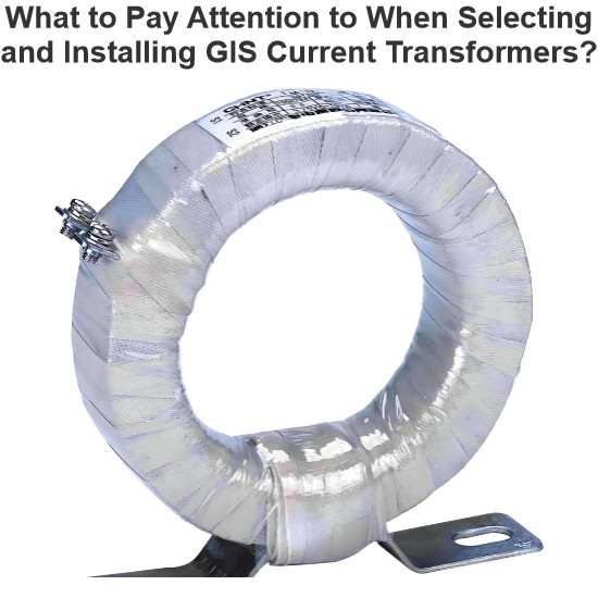
What to Pay Attention to When Selecting and Installing GIS Current Transformers?
Hi everyone, I'm James, and I've been working with current transformers (CTs) for 10 years. Today, I’ll talk about what you need to watch out for when selecting and installing GIS current transformers.Part 1: Key Considerations During Selection1. Accuracy ClassProtection-grade CTs: Used for relay protection — focus on overload capacity and transient response.Metering-grade CTs: Used for billing purposes — require high accuracy, usually 0.2S or 0.5S class.2. Rated Primary Curren
James
07/07/2025
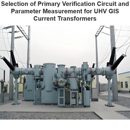
Selection of Primary Verification Circuit and Parameter Measurement for UHV GIS Current Transformers
In UHV GIS, current transformers are key to electric energy metering. Their accuracy determines power trade settlements, so on - site error verification perJJG1021 - 2007is needed. On - site, use power supplies, voltage regulators, and current boosters. Due to encapsulation in GIS, build test circuits via exposed grounding knives, bushings, and return conductors; right circuits simplify wiring and boost accuracy.Challenges like large test current, long circuits, and high impedance exist, but rea
Oliver Watts
07/07/2025
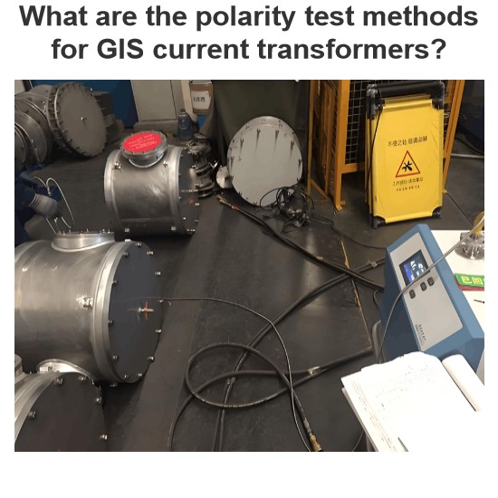
What are the polarity test methods for GIS current transformers?
I’m Oliver, an 8 - year current transformer testing pro. Today, let’s break down new and old polarity test methods for GIS current transformers—how they work and their pros/cons.1.Testing Methods1.1New MethodPre - test ops: Open FDS21/FDS22 fast disconnectors + DS23 disconnector. Close CB21 breaker, then ES21/ES22 grounding disconnectors. Disconnect ES21’s SF6 - shell ground.Wiring: Connect battery between ES21’s moving contact (negative grounded) + ground electrode
Oliver Watts
07/07/2025
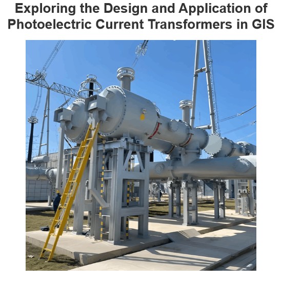
Exploring the Design and Application of Photoelectric Current Transformers in GIS
1.Design and Application Example of Photoelectric Current Transformer in GISThis article takes a 126kV GIS project as a specific example to deeply explore the design ideas and practical application of photoelectric current transformers in the GIS system. Since this GIS project was officially put into operation, the power system has remained stable, with no major failures occurring, and the operation status is relatively ideal.1.1 Design and Application Ideas of Photoelectric Current TransformerI
Dyson
07/07/2025
Inquiry
Download
Experts Electrical is dedicated to serving the personnel in the global power industry.
Join Experts Electrical, not only can you discover power equipment and power knowledge, but also canhnd like - minded friends!