What are the polarity test methods for GIS current transformers?
Oliver Watts
07/07/2025
1.2 Old Method
2 Method Comparison
Topics
Hey! I'm Oliver Watts, an electrical engineer in Inspection and Testing. With years of hands - on experience, I ensure electrical systems meet top safety and performance standards. Using advanced gear, I conduct diverse tests, easily spotting issues in both large - scale industrial and small - scale commercial setups. I love teaming up, sharing knowledge, and keeping up with industry regs. Also, I'm skilled at data analysis with software. If you're into electrical inspection or just want to chat engineering, reach out. Let's connect and explore!
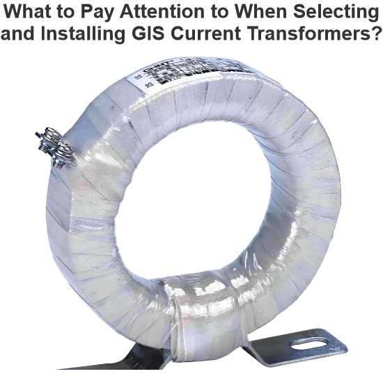
What to Pay Attention to When Selecting and Installing GIS Current Transformers?
Hi everyone, I'm James, and I've been working with current transformers (CTs) for 10 years. Today, I’ll talk about what you need to watch out for when selecting and installing GIS current transformers.Part 1: Key Considerations During Selection1. Accuracy ClassProtection-grade CTs: Used for relay protection — focus on overload capacity and transient response.Metering-grade CTs: Used for billing purposes — require high accuracy, usually 0.2S or 0.5S class.2. Rated Primary Curren
James
07/07/2025
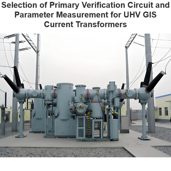
Selection of Primary Verification Circuit and Parameter Measurement for UHV GIS Current Transformers
In UHV GIS, current transformers are key to electric energy metering. Their accuracy determines power trade settlements, so on - site error verification perJJG1021 - 2007is needed. On - site, use power supplies, voltage regulators, and current boosters. Due to encapsulation in GIS, build test circuits via exposed grounding knives, bushings, and return conductors; right circuits simplify wiring and boost accuracy.Challenges like large test current, long circuits, and high impedance exist, but rea
Oliver Watts
07/07/2025
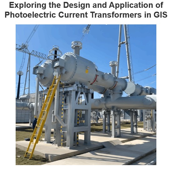
Exploring the Design and Application of Photoelectric Current Transformers in GIS
1.Design and Application Example of Photoelectric Current Transformer in GISThis article takes a 126kV GIS project as a specific example to deeply explore the design ideas and practical application of photoelectric current transformers in the GIS system. Since this GIS project was officially put into operation, the power system has remained stable, with no major failures occurring, and the operation status is relatively ideal.1.1 Design and Application Ideas of Photoelectric Current TransformerI
Dyson
07/07/2025
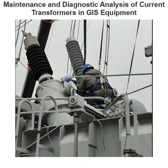
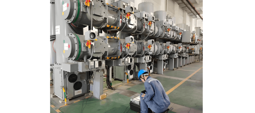
Maintenance and Diagnostic Analysis of Current Transformers in GIS Equipment
I'm Oliver, with 8 years of experience in current transformer testing. These are all practical experiences, shared with you1 Maintenance of Current TransformersHaving been in the business of current transformer testing for 8 years, I know a thing or two about their maintenance! The maintenance of current transformers is divided into minor repairs, intermediate repairs, and major overhauls.Minor repairs mainly involve opening the cover (if necessary) and changing the oil, usually carried out once
Oliver Watts
07/07/2025


