Aerially - mounted installations may supply several buildings. In such cases, transformers shall be installed at the pole location closest to the building with the highest load. If the span does not exceed 125 feet, the secondary wiring should lead directly to the served buildings; otherwise, intermediate poles are required.
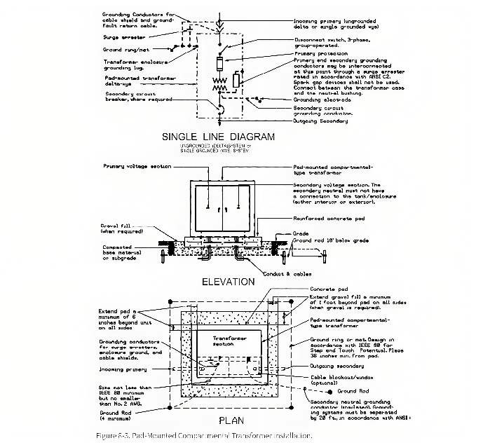
Ground - level mounting can be either the pad - mounted compartmental type or the unit substation type. Figure 8 - 3 shows a typical pad - mounted compartmental transformer installation.
The use of conventional - type (pole - mounted) transformers with separate primary and secondary protective devices is not permitted. This is because such installations are more hazardous, generally more difficult to maintain, require more space, and rarely result in significant cost savings since fencing is necessary.
Pad - mounted compartmental transformers should only be used outdoors, even if they are designed for both indoor and outdoor installation. Unit substation transformers can be used either indoors or outdoors.
Three - phase pad - mounted compartmental transformers can be in ANSI standard sizes up to 2500 kVA, but they shall not be used when the primary voltage exceeds 15 kV or when the fault current is so large that standard equipment cannot meet the required primary interrupting duty.
When choosing between pad - mounted compartmental transformers and unit substations (equipped with integral or non - integral load - center transformers), the following factors shall be considered: application scenarios, expansion potential, coordination of short - circuit and protective devices, sound engineering judgment, recognized industry practices, as well as the following considerations regarding operation, maintenance, and reliability:
- If operators frequently need to use instruments and switches, unit substations and integral or non - integral load - center transformers should be chosen. For pad - mounted compartmental transformers, instruments and operating devices are located inside a locked compartment and are not easily accessible.
- Pad - mounted compartmental transformers require the use of an insulated operating rod to operate the switch mechanism and disconnect the cable (due to the dead - front design requirement). However, the commonly used high - voltage switches in unit substations do not require special tools and are easier to operate.
- Unit substations and integral load - center transformers have fan - cooling functions, which can provide an additional 12% capacity under a temperature rise condition of 55/65 degrees Celsius. In contrast, self - cooled pad - mounted compartmental transformers do not have this function, and fans cannot be added to enhance the cooling capacity.
Pad - mounted transformers are typically used for residential and small - scale commercial power supply.
Pad - mounted transformers can be used for industrial, commercial, or industrial - related applications, provided that the following conditions are met: they supply power to only one building; metering devices and secondary switchgear can be installed within that building; and the coordination requirements for short - circuit and protective devices are fulfilled.
Unit substations and integral and/or non - integral load - center transformers will be used in industrial, large - scale commercial, and institutional applications that involve large loads, power supply to multiple buildings, and the need for secondary busbar protective devices.
Secondary unit substations with integral or non - integral outgoing sections should be used. Since neither type is tamper - proof, fencing is required, and the height of the fence should comply with the requirements of the National Electrical Safety Code (NESC). For 480Y/277V power supply systems, transformers with a capacity larger than 1500 kVA should be avoided; for 280Y/120V power supply systems, transformers with a capacity larger than 500 kVA should be avoided, taking into account the magnitude of the secondary fault current.
However, in some cases, it may be more feasible and cost - effective to equip 480Y/277V power supply systems with 2000 kVA transformers and use current - limiting fuses in conjunction with circuit breakers to limit the secondary fault current. The user agency (such as the Host/REQ CMD of the U.S. Air Force) will stipulate the requirements for demand meters.
Outdoor installations are preferred over indoor installations because of lower space costs. However, considering factors such as the length of secondary feeders, indoor installations may be necessary in some cases, or they may be more economically viable.
Outdoor installations shall comply with the National Electrical Code (NEC), MIL - HDBK - 1008A, and the National Electrical Safety Code (NESC). The installation location of the transformer shall ensure that in case of a transformer fire, the combustion products will not be drawn into the air intake of the Heating, Ventilation, and Air Conditioning (HVAC) system of adjacent buildings.
The location of pad - mounted transformers shall be in line with the architectural design concept and be protected from vehicular impact. Coordination with the architecture can be achieved by properly planning the relative position to the landscape, planting shrubs around the transformer, or using screened fences. The primary power supply lines for pad - mounted transformers shall be underground. For the secondary connection to the building, underground cables or bus ducts can be used, but no more than six underground cables per phase shall be used in parallel, as overly complex connections may lead to maintenance and space - related issues.
Indoor installations shall comply with the National Electrical Code (NEC) and MIL - HDBK - 1008A. The transformer vault shall be located on the exterior wall of the building, have vents to the outside, and be accessible only from outside the building under normal design conditions.
The intake fans and louvers of the Heating, Ventilation, and Air Conditioning (HVAC) system shall be interlocked with the smoke detectors and rate - of - rise detectors in the transformer vault and/or related rooms. If a fire occurs in the transformer vault and/or related rooms, these detectors shall de - energize the HVAC air intake. However, if the HVAC air intake is located on the roof of the building or on the opposite side from the transformer vault, such interlocking is not necessary.
Signs shall be posted at the access doors of the transformer vault indicating the appropriate fire - fighting equipment and procedures. Pipes and ducts shall not be routed above indoor transformers.