Zero Power Factor Characteristic (ZPFC)
The Zero Power Factor Characteristic (ZPFC) of a generator represents a curve that illustrates the relationship between the armature terminal voltage and the field current. In this test, the generator operates at synchronous speed with a constant rated armature current and a zero lagging power factor. The Zero Power Factor Characteristic is also known as the Potier Characteristic.
To maintain a very low power factor, the alternator is loaded using reactors or an under - excited synchronous motor. The shape of the ZPFC closely resembles that of the Open Circuit Characteristic (O.C.C.).
The phasor diagram corresponding to a zero power factor lagging condition is presented as follows:
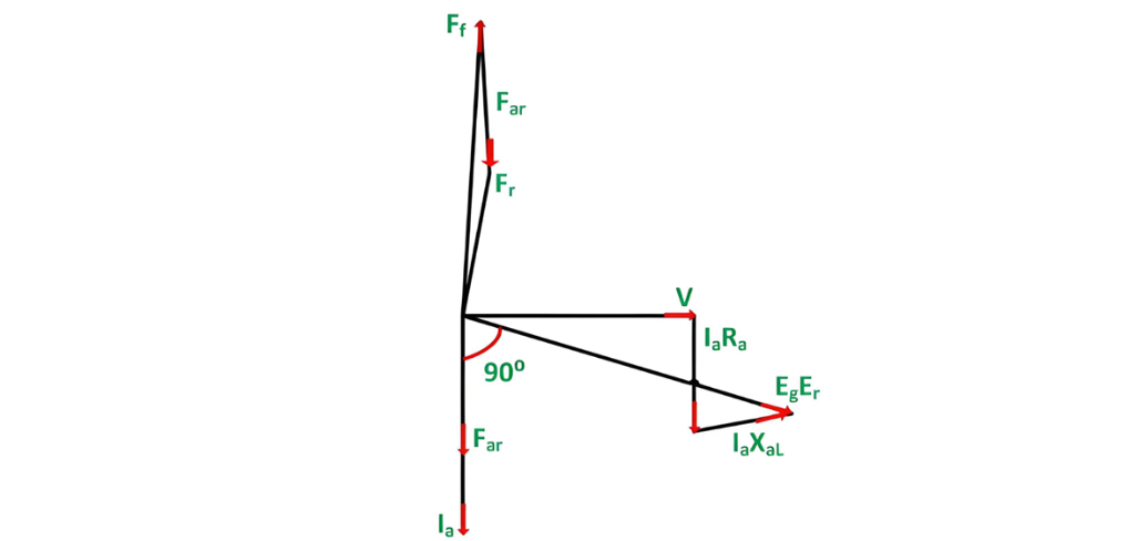
In the phasor diagram depicted above, the terminal voltage V serves as the reference phasor. Under the condition of zero power factor lagging, the armature current Ia lags behind the terminal voltage V by exactly 90 degrees. The voltage drop Ia Ra (where Ra is the armature resistance) is drawn parallel to the armature current Ia, while Ia XaL (with XaL being the armature leakage reactance) is plotted perpendicular to Ia.

Eg is the generated voltage per phase.
The phasor diagram at ZPF lagging with the armature resistance Ra neglected is shown below:
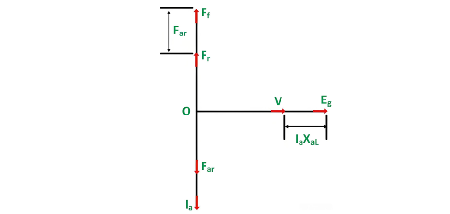
Far represents the armature reaction magnetomotive force (MMF). It is in phase with the armature current Ia, meaning their phase relationship is such that they vary simultaneously.
Ff denotes the MMF of the main field winding, commonly referred to as the field MMF. This is the magnetic - driving force generated by the field winding of the generator.Frstands for the resultant MMF, which is the combined effect of the armature reaction MMF and the field MMF within the machine's magnetic circuit.
The field MMF Ff is calculated by subtracting the armature reaction MMF Far from the resultant MMF Fr. Mathematically, this relationship is expressed as

As can be observed from the aforementioned phasor diagram, the terminal voltage V, the reactance voltage drop Ia XaL}, and the generated voltage Eg all exhibit the same phase. Consequently, the terminal voltage V is approximately equal to the arithmetic difference between the generated voltage Eg and the reactance voltage drop Ia XaL.

The three MMF phasor Ff, Fr and Far are in phase. Their magnitudes are related by the equation shown below:

The two equations mentioned above, namely equation (1) and equation (2), serve as the fundamental building blocks for the Potier triangle.When both sides of equation (2) are divided by Tf - where Tf represents the effective number of turns per pole on the rotor field - the equation can be transformed into its equivalent form in terms of field current. As a result,

Based on the above - derived equation, the field current can be obtained by summing up the resultant current and the armature reaction current.
The Electricity Encyclopedia is dedicated to accelerating the dissemination and application of electricity knowledge and adding impetus to the development and innovation of the electricity industry.

