Three Phase System
Definition and Characteristics of Three - Phase Systems
A three - phase system is defined as an electrical system consisting of three phases. In this setup, electric current flows through three distinct wires, while a neutral wire serves as a pathway for fault current to safely discharge into the earth. Alternatively, it can be described as a system that utilizes three wires for the processes of electrical generation, transmission, and distribution. Additionally, a three - phase system can function as a single - phase system by extracting one of its phases along with the neutral wire. In a balanced three - phase system, the sum of the line currents is precisely zero, and the phases are separated by an angular displacement of 120º.
A typical three - phase system employs four wires: three current - carrying conductors and one neutral wire. Notably, the cross - sectional area of the neutral conductor is usually half that of the live wires. The current in the neutral wire is equal to the vector sum of the line currents of the three phases. Mathematically, it is equivalent to √3 times the zero - phase - sequence component of the current.
Three - phase systems offer numerous significant advantages. Compared to single - phase systems, they require fewer conductors, reducing infrastructure costs. They also ensure a continuous power supply to the load, enhancing the reliability of electrical service. Moreover, three - phase systems are renowned for their higher efficiency and minimized power losses during transmission and operation.
Three - phase voltages are generated within a generator, producing three sinusoidal voltages of equal magnitude and frequency, yet phase - shifted by 120º relative to each other. This configuration provides an uninterruptible power supply. In the event that one phase of the system experiences a disturbance, the remaining two phases can continue to deliver power, maintaining essential electrical services. It's important to note that in a balanced three - phase system, the magnitude of the current in any one phase is equal to the vector sum of the currents in the other two phases, adhering to the principles of electrical circuit theory.
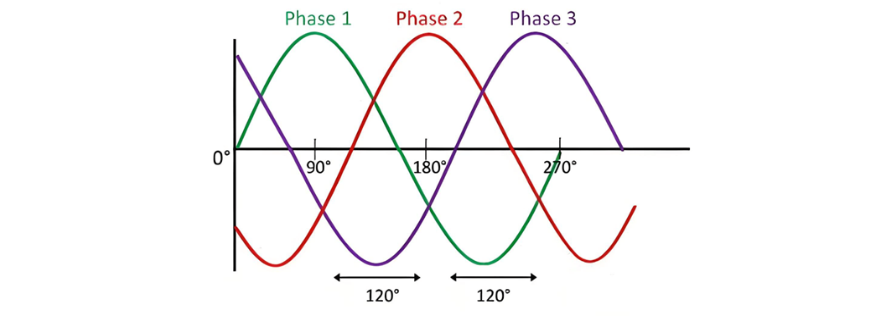
A 120º phase difference among the three phases is crucial for the proper and reliable operation of a three - phase system. Without this precise phase relationship, the system is highly vulnerable to damage, which can lead to disruptions in power supply, equipment failures, and potential safety hazards.
Types of Connections in Three - Phase System
Three - phase systems can be configured in two primary ways: star connection and delta connection. Each of these connection methods has distinct characteristics and applications, which are detailed below.
Star Connection
The star connection, also known as the Y - connection, utilizes four wires: three phase conductors and one neutral conductor. This type of connection is particularly well - suited for long - distance electrical transmission. The presence of the neutral point is a key advantage. It serves as a pathway for unbalanced currents, allowing them to flow safely to the earth. By effectively handling these unbalanced currents, the star connection helps maintain the overall balance of the electrical system, reducing the risk of overloading and ensuring stable power delivery over extended distances.
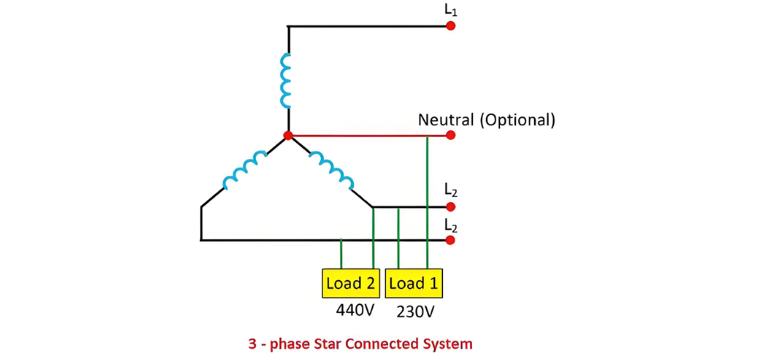
In a star - connected three - phase system, two distinct voltage levels are available: 230 V and 440 V. Specifically, the voltage measured between a single phase conductor and the neutral is 230 V, while the voltage between any two phase conductors amounts to 440 V. This dual - voltage characteristic makes the star connection versatile for various electrical applications, catering to both low - voltage domestic and higher - voltage industrial requirements.
Delta Connection
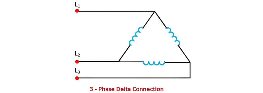
The delta connection, in contrast, employs only three wires and lacks a neutral point, as illustrated in the figure below. One of the defining features of the delta connection is that the line voltage is identical to the phase voltage. This configuration simplifies the electrical setup in certain scenarios, particularly when the absence of a neutral wire is acceptable and when the system design benefits from the direct equivalence of line and phase voltages.
Connection of Loads in Three - Phase Systems
In a three - phase electrical system, loads can be connected in either a star (Y) or delta (Δ) configuration. These two connection methods have distinct electrical characteristics and applications. The diagrams below illustrate how three - phase loads are connected in both the delta and star arrangements, providing a clear visual representation of their structural differences and electrical behaviors.
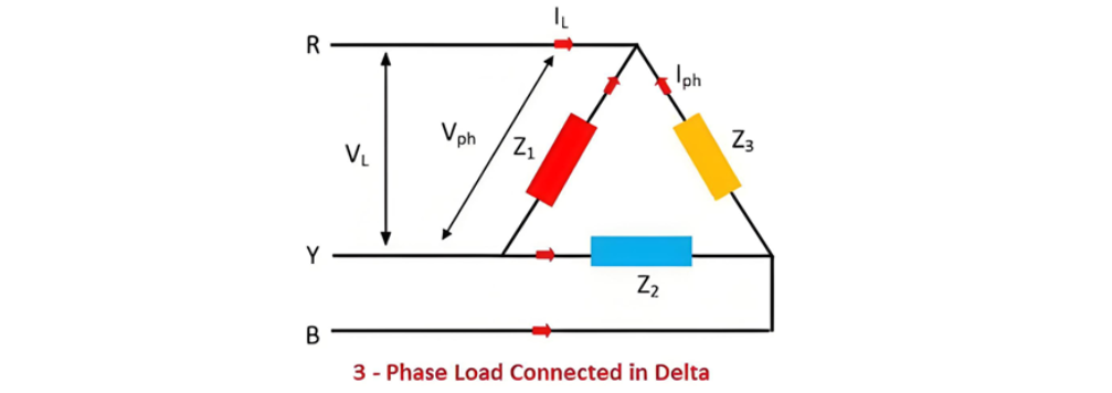
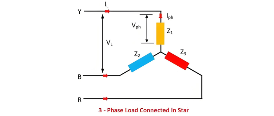
In a three - phase electrical system, the load can be categorized as either balanced or unbalanced. A three - phase load is deemed balanced when the three individual loads (represented by impedances) Z1, Z2, and Z3 exhibit both identical magnitudes and phase angles. Under such balanced conditions, not only do all the phase voltages maintain equal magnitudes, but the line voltages also share this characteristic of being equal in magnitude. This symmetry in voltage and impedance values results in a more stable and efficient electrical operation, minimizing power losses and ensuring uniform distribution of electrical energy across the system.
The Electricity Encyclopedia is dedicated to accelerating the dissemination and application of electricity knowledge and adding impetus to the development and innovation of the electricity industry.

