Discussion on Faults of Rural Power Grid Distribution Transformers

Felix Spark
05/14/2025
1. Introduction
Due to long - term operation, faults and accidents of distribution transformers in rural power grids cannot be completely avoided. These faults and accidents are caused by a multitude of factors, such as external forces like damage and impact, and irresistible natural disasters such as lightning strikes. Meanwhile, in some rural areas, the low - voltage lines are inadequately maintained, frequently resulting in overloading and short - circuits, which cause distribution transformers to burn out. This has become a major factor contributing to failures.
To prevent distribution transformers from burning out and reduce their operational failures in rural power grids, this paper summarizes and analyzes some typical fault types and causes of distribution transformers, explores preventive measures, further investigates and addresses potential hazards and weak links of distribution transformers, effectively prevents and curbs the occurrence of burning - out faults of distribution transformers, and thereby enhances the power supply reliability of rural power grids.
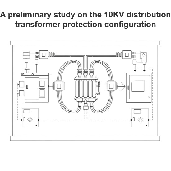
Currently, the distribution transformers used in rural power grids are mainly oil - immersed distribution transformers. The faults of such transformers are commonly classified into internal and external faults. Internal faults refer to various malfunctions occurring inside the transformer tank. The main types include inter - phase short - circuits between windings, turn - to - turn short - circuits within windings, and grounding faults where windings or lead - outs contact the outer casing. External faults are various malfunctions occurring on the insulating bushings outside the transformer tank and their lead - outs. The main types are grounding due to flashover or breakage of insulating bushings, and inter - phase short - circuits or grounding of low - voltage outlet lines.
Since the faults of distribution transformers cover a wide range, there are numerous specific classification methods. For example, from the perspective of circuit loops, they are mainly classified into circuit faults, magnetic circuit faults, and oil - circuit faults. If classified according to the main structure of the distribution transformer, they can be divided into winding faults, core faults, oil - quality faults, and accessory faults. Conventionally, the fault types of distribution transformers are generally classified based on common fault - prone areas, such as insulation faults, core faults, tap - changer faults, etc. Among them, the distribution transformer outlet short - circuit fault has the most serious impact on the transformer itself and the highest occurrence rate currently. Additionally, there are also distribution transformer leakage faults, etc. All these different types of faults may represent thermal faults, electrical faults, or both thermal and discharge faults simultaneously. However, the leakage fault of a distribution transformer may not exhibit thermal or electrical fault characteristics under normal circumstances.
Therefore, it is difficult to categorize the fault types of distribution transformers within a specific framework. This paper adopts relatively common and general fault types of distribution transformers, such as short - circuit faults, discharge faults, insulation faults, core faults, tap - changer faults, oil - gas leakage faults, external - force damage faults, and fuse protection faults. Each type is discussed separately in terms of its cause and corresponding technical measures.
2. Fault Analysis of Distribution Transformers
2.1 Short - Circuit Faults
2.1.1 Fault Cause Analysis
2.1 Short - Circuit Faults
2.1.1 Fault Cause Analysis
Short - circuit faults of distribution transformers mainly refer to outlet short - circuits of distribution transformers, as well as short - circuits between internal lead - outs or windings to the ground, and short - circuits between phases, which lead to failures.
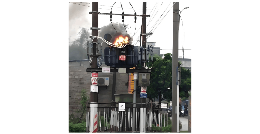
During the normal operation of distribution transformers, the damage caused by outlet short - circuit faults is relatively severe. According to relevant statistics, faults directly resulting from short - circuit fault current impacts on distribution transformers in rural power grids account for approximately 40% of all faults. There are numerous such cases. In particular, when a low - voltage outlet short - circuit occurs in a distribution transformer, the windings generally need to be replaced. In severe cases, all windings may need to be replaced, resulting in extremely serious consequences and losses. Therefore, it should be given sufficient attention.
The impacts of outlet short - circuits on distribution transformers mainly include the following two aspects:
Insulation Overheating Fault Caused by Short - Circuit Current
Due to inadequate maintenance of some rural low - voltage lines, overloading and short - circuits frequently occur. When a distribution transformer experiences a sudden short - circuit, its high - and low - voltage windings may simultaneously pass short - circuit currents dozens of times the rated value. This generates a large amount of heat, causing the distribution transformer to overheat severely and the coil temperature to rise rapidly, leading to insulation aging. When the distribution transformer's ability to withstand short - circuit current is insufficient and its thermal stability is poor, the insulation material of the distribution transformer will be severely damaged, resulting in breakdown and damage to the distribution transformer.
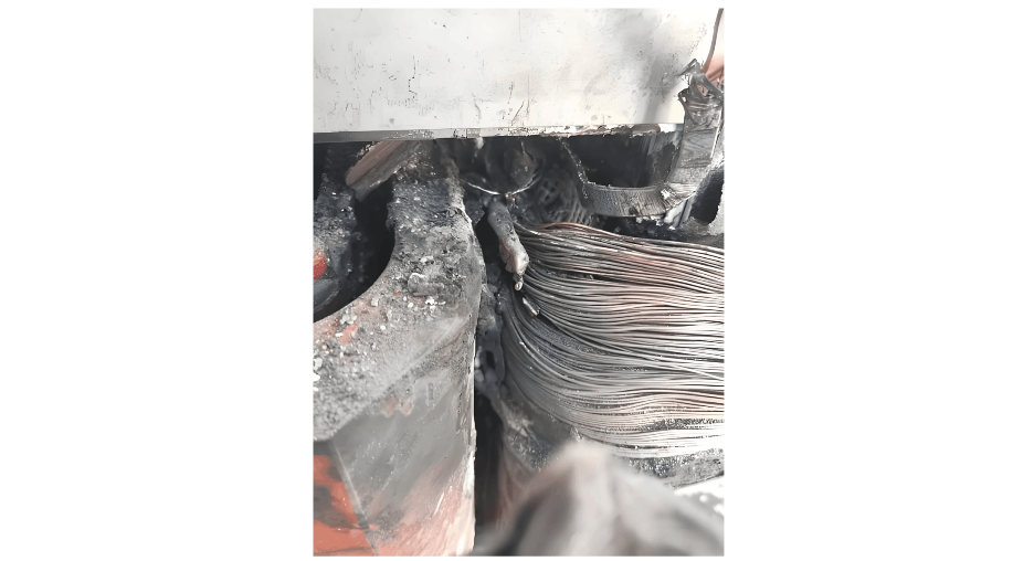
Winding Deformation Fault Caused by Short - Circuit Electrodynamic Force
When a distribution transformer is impacted by a short - circuit, if the short - circuit current is small and the fuse blows correctly, the winding deformation will be minor. If the short - circuit current is large and the fuse blows with a delay or fails to blow, the secondary side will generate a short - circuit current 20 - 30 times higher than the rated current. The primary side of the distribution transformer will inevitably generate a large current to counteract the demagnetizing effect of the secondary - side short - circuit current. The large current generates a significant mechanical stress inside the coil, causing the coil to compress, shift, or deform, the insulation pads and plates to loosen, the core clamping bolts to become slack, the high - voltage coil to distort or burst, and ultimately leading to a failure of the distribution transformer. At the same time, the windings are subjected to a relatively large electromagnetic torque, and the insulation material flakes off, exposing the wire body and causing inter - turn short - circuits. For minor deformations, if not repaired in a timely manner, such as restoring the position of the pads, tightening the pressure nails of the windings and the pull - plates and pull - rods of the yoke, and strengthening the clamping force of the lead - outs, the cumulative effect after multiple short - circuit impacts will also damage the distribution transformer.
Insulation Overheating Fault Caused by Short - Circuit Current
Due to inadequate maintenance of some rural low - voltage lines, overloading and short - circuits frequently occur. When a distribution transformer experiences a sudden short - circuit, its high - and low - voltage windings may simultaneously pass short - circuit currents dozens of times the rated value. This generates a large amount of heat, causing the distribution transformer to overheat severely and the coil temperature to rise rapidly, leading to insulation aging. When the distribution transformer's ability to withstand short - circuit current is insufficient and its thermal stability is poor, the insulation material of the distribution transformer will be severely damaged, resulting in breakdown and damage to the distribution transformer.
Winding Deformation Fault Caused by Short - Circuit Electrodynamic Force
When a distribution transformer is impacted by a short - circuit, if the short - circuit current is small and the fuse blows correctly, the winding deformation will be minor. If the short - circuit current is large and the fuse blows with a delay or fails to blow, the secondary side will generate a short - circuit current 20 - 30 times higher than the rated current. The primary side of the distribution transformer will inevitably generate a large current to counteract the demagnetizing effect of the secondary - side short - circuit current. The large current generates a significant mechanical stress inside the coil, causing the coil to compress, shift, or deform, the insulation pads and plates to loosen, the core clamping bolts to become slack, the high - voltage coil to distort or burst, and ultimately leading to a failure of the distribution transformer. At the same time, the windings are subjected to a relatively large electromagnetic torque, and the insulation material flakes off, exposing the wire body and causing inter - turn short - circuits. For minor deformations, if not repaired in a timely manner, such as restoring the position of the pads, tightening the pressure nails of the windings and the pull - plates and pull - rods of the yoke, and strengthening the clamping force of the lead - outs, the cumulative effect after multiple short - circuit impacts will also damage the distribution transformer.
2.1.2 Measures to Reduce Short - Circuit Faults
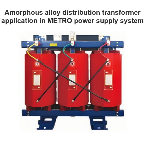
- Optimization of Selection Requirements. When selecting a distribution transformer, choose one that can smoothly pass the short - circuit test. Reasonably determine the capacity of the distribution transformer and select its short - circuit impedance rationally. Try to use energy - efficient S11 - type distribution transformers and phase out high - energy - consumption transformers.
- Optimization of Operating Conditions and Environment. Improve the insulation level of power lines, especially the insulation level of the low - voltage outlet lines of the distribution transformer over a certain distance. Meanwhile, raise the standards for the safety corridor and safety distance requirements of low - voltage lines to reduce the impact and hazards of nearby - area faults. This includes paying attention to the installation and maintenance quality of low - voltage dropper terminals (since the explosion of low - voltage terminals is mostly equivalent to a secondary short - circuit), preventing small animals from intruding, and improving the quality requirements for low - voltage fuses to prevent situations such as fuses not blowing.
- Optimization of Operating Modes. When determining the operating mode, calculate the short - circuit current and limit its hazards. In particular, prevent the distribution transformer from operating under overload. Try to calculate and adjust the electrical load of the distribution transformer.
- Improvement of Operation Management Level. First, prevent short - circuit impacts caused by misoperation. Strengthen the timely monitoring and maintenance of distribution transformers, promptly detect the degree of deformation of distribution transformers, and ensure their safe operation. At the same time, increase the inspection efforts on the power consumption of users in the distribution transformer area to prevent overloading problems caused by user power theft.
2.2 Discharge Faults
Based on the energy density of the discharge, the discharge faults of distribution transformers are commonly classified into partial discharge, spark discharge, and high - energy discharge. Discharge has two types of destructive effects on insulation: one is that the discharge particles directly bombard the insulation, causing local insulation damage and gradually expanding it until the insulation breaks down. The other is that the chemical action of active gases such as heat, ozone, and nitrogen oxides generated by the discharge corrodes the local insulation, increases the dielectric loss, and ultimately leads to thermal breakdown.
2.2.1 Partial Discharge Faults of Distribution Transformers
Partial discharge refers to a non - through - type discharge phenomenon that occurs at the edges of air gaps, oil films, or conductors within the insulation structure under the action of voltage. At the beginning, partial discharge is a low - energy discharge. When this kind of discharge occurs inside a distribution transformer, the situation is relatively complex. According to different insulation media, partial discharge can be divided into partial discharge in bubbles and partial discharge in oil. According to insulation locations, it includes partial discharge in cavities of solid insulation, at electrode tips, in oil - corner gaps, in oil gaps between oil and insulation paperboards, and along the surface of solid insulation in oil. The reasons for partial discharge are as follows:
- When there are bubbles in the oil or cavities in the solid insulation material, due to the small dielectric constant of the gas, it bears a high electric field strength under alternating voltage, but its withstand voltage strength is lower than that of oil and paper insulation materials. Therefore, discharge is likely to occur first in the air gap.
- Influence of external environmental conditions. For example, if the oil treatment is incomplete and bubbles precipitate from the oil, it will cause discharge.
- Due to poor manufacturing quality. For example, discharge occurs at some parts with sharp corners. Bubbles, debris, and moisture are introduced, or due to external temperature - related factors such as paint nodules, they bear a relatively large electric field strength.
- Discharge caused by poor contact between metal parts or conductors. Although the energy density of partial discharge is not large, if it develops further, it will form a vicious cycle of discharge, ultimately leading to the breakdown or damage of the equipment and causing serious burnout accidents.
2.2.2 Spark Discharge Faults of Distribution Transformers
Generally, spark discharge does not quickly cause insulation breakdown. It is mainly reflected in abnormal oil chromatographic analysis, an increase in partial discharge quantity, or light gas. It is relatively easy to detect and handle, but sufficient attention should be paid to its development. There are mainly two reasons for spark discharge:
Spark Discharge Caused by Floating Potential. In high - voltage power equipment, a certain metal part, due to structural reasons or poor contact during transportation and operation, is disconnected and is located between the high - voltage and low - voltage electrodes, dividing the voltage according to its impedance. The potential to the ground generated on this metal part is called the floating potential. The electric field strength near an object with a floating potential is relatively concentrated, often gradually burning out the surrounding solid dielectric or carbonizing it.
It also causes the insulating oil to decompose a large amount of characteristic gases under the action of the floating potential, resulting in an abnormal result of the insulating oil chromatographic analysis. Floating discharge may occur in metal parts at high potential inside the distribution transformer, such as the regulating winding, when the grading ball of the bushing and the no - load tap - changer shift fork have a floating potential. For parts at ground potential, such as the silicon steel sheet magnetic shielding and various metal bolts for fastening, if their connection to the ground is loose or detached, it will lead to floating - potential discharge. Poor contact at the end of the high - voltage bushing of the distribution transformer can also form a floating potential and cause spark discharge.
Spark Discharge Caused by Impurities in Oil
The main cause of spark discharge faults in distribution transformers is the influence of impurities in the oil. These impurities are composed of moisture, fibrous substances (mainly damp fibers), etc. The dielectric constant ε of water is approximately 40 times that of the distribution transformer oil. In an electric field, the impurities are first polarized and attracted to the area with the strongest electric field intensity, namely near the electrodes, and are arranged in the direction of the electric field lines. Thus, an impurity "bridge" is formed near the electrodes.
The main cause of spark discharge faults in distribution transformers is the influence of impurities in the oil. These impurities are composed of moisture, fibrous substances (mainly damp fibers), etc. The dielectric constant ε of water is approximately 40 times that of the distribution transformer oil. In an electric field, the impurities are first polarized and attracted to the area with the strongest electric field intensity, namely near the electrodes, and are arranged in the direction of the electric field lines. Thus, an impurity "bridge" is formed near the electrodes.
The conductivity and dielectric constant of the "bridge" are both greater than those of the distribution transformer oil. According to the principles of electromagnetic fields, the presence of the "bridge" distorts the electric field in the oil. Since the dielectric constant of the fibers is small, the electric field in the oil at the ends of the fibers is strengthened. Therefore, the discharge first occurs and develops in this part of the oil. The oil dissociates under a high - field - strength environment, decomposing into gases, which causes the bubbles to increase in size and the dissociation to strengthen. Subsequently, the process gradually develops, leading to spark discharge in the entire oil gap through the gas channel. So, spark discharge may occur at a relatively low voltage.
If the distance between the electrodes is not large and there are enough impurities, the "bridge" may connect the two electrodes. At this time, due to the relatively high conductivity of the "bridge", a large current flows along the "bridge" (the magnitude of the current depends on the capacity of the power supply), causing the "bridge" to heat up intensely. The moisture and the nearby oil in the "bridge" boil and vaporize, creating a gas channel - the "bubble bridge", and spark discharge occurs.
If the fibers are not damp, the conductivity of the "bridge" is very small, and its influence on the spark discharge voltage of the oil is also relatively small; conversely, the influence is greater. Therefore, the spark discharge of the distribution transformer oil caused by impurities is related to the heating process of the "bridge". When an impulse voltage acts or the electric field is extremely non - uniform, it is not easy for the impurities to form a "bridge", and their effect is only limited to distorting the electric field. The spark discharge process mainly depends on the magnitude of the applied voltage.
2.2.3 Arc Discharge Faults of Distribution Transformers
Arc discharge is a high - energy discharge, which is commonly seen as insulation breakdown between winding turns or layers. Other common faults include lead breakage, flashover to the ground, and arcing of tap - changers.
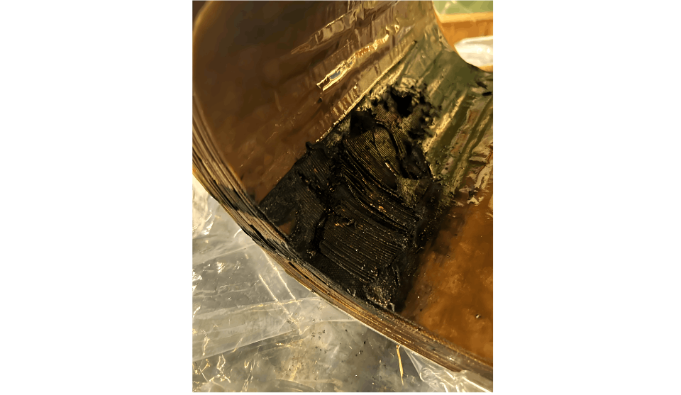
- Influence of Arc Discharge. Due to the high energy density of arc discharge faults, gas is generated rapidly. It often impacts the dielectric in the form of electron avalanches, causing the insulating paper to perforate, char, or carbonize, deforming or melting and burning the metal materials. In severe cases, it may cause equipment damage or even explosions. Such accidents are generally difficult to predict in advance and have no obvious omens, often emerging in a sudden manner.
- Gas Characteristics of Arc Discharge. After an arc discharge fault occurs, the distribution transformer oil also carbonizes and turns black. The main components of the characteristic gases in the oil are H2 and C2H2, followed by C2H6 and CH4. When the discharge fault involves solid insulation, CO and CO2 will also be generated.In summary, the three forms of discharge have both differences and certain connections. The differences refer to the discharge energy level and gas composition, while the connection is that partial discharge is a precursor to the other two forms of discharge, and the latter two are inevitable results of the development of the former. Since the faults occurring inside distribution transformers are often in a state of gradual development, and most of them are not single - type faults, but rather one type is accompanied by another type, or several types occur simultaneously. Therefore, more careful analysis and specific treatment are required.
2.3 Insulation Faults
Currently, the most widely used distribution transformers in rural power grids are oil - immersed transformers. The insulation of a distribution transformer refers to the insulation system composed of its insulation materials. It is a fundamental condition for the normal operation of the distribution transformer, and the service life of the distribution transformer is determined by the lifespan of the insulation materials (such as oil - paper or resin). Practical experience has proven that most of the damage and faults of distribution transformers are caused by the damage of the insulation system.
Therefore, protecting the normal operation of the distribution transformer and strengthening the reasonable maintenance of the insulation system can, to a large extent, ensure a relatively long service life for the distribution transformer. Preventive and predictive maintenance are the keys to extending the service life of distribution transformers and improving power supply reliability.
In oil - immersed distribution transformers, the main insulation materials are insulating oil and solid insulation materials such as insulating paper, cardboard, and wooden blocks. The so - called aging of the distribution transformer insulation means that these materials decompose under the influence of environmental factors, reducing or losing their insulation strength.
2.3.1 Solid Paper Insulation Faults
Solid insulation is one of the main components of the insulation of oil - immersed distribution transformers, including insulating paper, insulating board, insulating pad, insulating coil, insulating binding tape, etc. Its main component is cellulose. After the insulating paper ages, its degree of polymerization and tensile strength gradually decrease, and water, CO, and CO2 are generated. In addition, furfural (furfuraldehyde) is also produced. Most of these aging products are harmful to electrical equipment. They can reduce the breakdown voltage and volume resistivity of the insulating paper, increase the dielectric loss, decrease the tensile strength, and even corrode the metal materials in the equipment.
2.3.2 Liquid Oil Insulation Faults
Reasons for the Deterioration of Distribution Transformer Oil
Contamination means that moisture and impurities are mixed into the oil. These are not oxidation products of the oil. The insulation performance of contaminated oil deteriorates, the breakdown electric field strength decreases, and the dielectric loss angle increases.
Deterioration is the result of oil oxidation. This oxidation does not only refer to the oxidation of hydrocarbons in pure oil but also includes the acceleration of the oxidation process by impurities in the oil, especially copper, iron, and aluminum metal shavings.
Deterioration is the result of oil oxidation. This oxidation does not only refer to the oxidation of hydrocarbons in pure oil but also includes the acceleration of the oxidation process by impurities in the oil, especially copper, iron, and aluminum metal shavings.
Oxygen comes from the air inside the distribution transformer. Even in a fully - sealed distribution transformer, there is still about 0.25% of oxygen by volume. Oxygen has a relatively high solubility, so it occupies a relatively high proportion among the dissolved gases in the oil.
When the distribution transformer oil oxidizes, moisture as a catalyst and heat as an accelerator cause the distribution transformer oil to generate sludge. Its main impacts are as follows: under the action of the electric field, the sediment particles are large; the impurities concentrate in the area with the strongest electric field, forming a conductive "bridge" for the insulation of the distribution transformer; the sediment is not uniform but forms separate slender strips, and it may be arranged in the direction of the electric field lines, which undoubtedly hinders heat dissipation, accelerates the aging of insulation materials, and leads to a decrease in insulation resistance and insulation level.
The Process of Distribution Transformer Oil Deterioration
During the deterioration process of the oil, the main products in each stage are peroxides, acids, alcohols, ketones, and sludge.In the early deterioration stage, the peroxides generated in the oil react with the insulating fiber materials to form oxidized cellulose, which deteriorates the mechanical strength of the insulating fibers, causing embrittlement and insulation shrinkage. The generated acids are a kind of viscous fatty acid. Although its corrosiveness is not as strong as that of mineral acids, its growth rate and impact on organic insulation materials are significant.
In the later deterioration stage, sludge is generated. When acids erode copper, iron, insulating paint, and other materials, sludge is produced. It is a viscous, asphalt - like polymeric conductive substance that can moderately dissolve in the oil. Under the action of the electric field, it is generated very quickly and adheres to the insulation materials or the edges of the distribution transformer tank, deposits in the oil pipes and radiator fins of the cooler, etc., increasing the operating temperature of the distribution transformer and reducing its electrical withstand strength.
The oxidation process of the oil is composed of two main reaction conditions. One is that the acid value in the distribution transformer oil is too high, making the oil acidic. The other is that the oxides dissolved in the oil are transformed into compounds insoluble in the oil, gradually deteriorating the quality of the distribution transformer oil.
2.3.3 Winding Insulation Moisture Ingress
Winding insulation moisture ingress is mainly caused by poor - quality insulating oil or a decrease in the oil level. The main reasons are as follows:
- Before the distribution transformer is put into operation, if it is in a humid place or a rainy area with high humidity, moisture will invade and cause the insulation to get damp.
- During storage, transportation, and operation, improper maintenance may lead to moisture, impurities, or other oil contaminants mixing into the distribution transformer oil, greatly reducing the insulation strength.
- During the manufacturing process, if the inner layer of the winding is not impregnated thoroughly and dried completely, or if the winding lead joints are not welded properly, incomplete insulation may cause inter - turn and inter - layer short - circuits. When approaching or reaching the service life, the insulation naturally becomes charred and black, and the insulation characteristics decline, which is the main cause of faults in old distribution transformers.
- In some old distribution transformers that have not been maintained for a long time, for various reasons, the oil level drops, and the insulating oil comes into extensive and long - term contact with the air. A large amount of moisture in the air enters the insulating oil, reducing the insulation strength.
2.3.4 Main Factors Affecting Distribution Transformer Insulation Faults
- The main factors affecting the insulation performance of distribution transformers include temperature, humidity, oil protection method, and over - voltage influence.
Influence of Temperature. Power distribution transformers use oil - paper insulation. At different temperatures, there are different equilibrium relationship curves for the water content in the oil and paper. Generally, when the temperature rises, the water in the paper is released into the oil; conversely, the paper absorbs water from the oil. Therefore, when the temperature is relatively high, the micro - water content in the insulating oil of the distribution transformer is relatively large; otherwise, it is small. - The service life of a distribution transformer depends on the degree of insulation aging, and the aging of the insulation depends on the operating temperature.
Influence of Humidity. The presence of moisture will accelerate the degradation of cellulose. Trace amounts of moisture in the insulating oil are one of the important factors affecting insulation characteristics. The presence of trace moisture in the insulating oil is extremely harmful to the electrical and physical - chemical properties of the insulation medium. Moisture can reduce the spark discharge voltage of the insulating oil, increase the dielectric loss factor tgδ, accelerate the aging of the insulating oil, and deteriorate the insulation performance. Equipment moisture ingress not only reduces the operational reliability and service life of electrical equipment but may also cause equipment damage and even endanger personal safety. - Influence of Over - Voltage.
- Influence of Transient Over - Voltage. The phase - to - ground voltage generated during the normal operation of a three - phase distribution transformer is 58% of the phase - to - phase voltage. However, when a single - phase fault occurs, the voltage on the main insulation for a neutral - grounded system will increase by 30%, and for a non - neutral - grounded system, it will increase by 73%. Therefore, the insulation may be damaged.
- Influence of Lightning Over - Voltage. Due to the steep wavefront of lightning over - voltage, the voltage distribution on the winding insulation (inter - turn and insulation) is very uneven. It may leave discharge traces on the insulation, thus damaging the solid insulation, such as the explosion of low - voltage terminal insulators.
- Influence of Switching Over - Voltage. Since the wavefront of switching over - voltage is quite gentle, the voltage distribution is approximately linear. When the switching over - voltage wave is transferred from one winding to another, it is approximately proportional to the number of turns between the two windings. Therefore, it is easy to cause deterioration and damage to the main insulation or inter - phase insulation.
- Influence of Short - Circuit Electrodynamic Force. The electrodynamic force during an outlet short - circuit may cause the windings of the distribution transformer to deform and the leads to shift, thus changing the original insulation distance. This makes the insulation heat up, accelerates aging, or causes damage, resulting in discharge, arcing, and short - circuit faults.
In summary, understanding the insulation performance of distribution transformers and conducting reasonable operation and maintenance directly affect the safe operation, service life, and power supply reliability of distribution transformers. Power distribution transformers are important and key main equipment in rural power grids. As operation and maintenance personnel and managers of distribution transformers, it is necessary to understand and master the insulation structure, material properties, process quality, maintenance methods, and scientific diagnostic techniques of power distribution transformers, and carry out optimized and reasonable operation management to ensure the efficiency, service life, and power supply reliability of power distribution transforme.
2.4 Other Faults
2.4.1 Core Faults
2.4.1 Core Faults
- Multiple - Point Grounding of the Core
- When the bushing of the through - bolt of the core clamping plate is damaged and comes into contact with the core, it forms multiple - point grounding, causing local overheating of the core and damaging the coil insulation.
- There are metal foreign objects or metal powder between the core and the clamping plate. Under the action of electromagnetic force, a "metal bridge" is formed, leading to multiple - point grounding.
- The insulation between the core and the clamping plate is damp or damaged in multiple places, resulting in low - resistance grounding at multiple points between the core and the clamping plate.
- Short - Circuit of Core Silicon Steel Sheets
- Although the silicon steel sheets are coated with insulating paint, its insulation resistance is small and can only cut off eddy currents. When the insulating paint on the surface of the silicon steel sheets ages naturally or is damaged due to long - term operation, a large eddy - current loss will be generated, causing local overheating of the core and resulting in insulation breakdown and short - circuit of the distribution transformer windings, which may lead to burning.
2.4.2 No - Load Tap - Changer Faults
- Exposure and Moisture Ingress of the Tap - Changer:Due to oil leakage at the general cap, bushing, tap - changer, end cover, oil valve, etc., the tap - changer is exposed to the air for a long time. Moreover, since the oil level indicator of the distribution transformer is set in the middle of the oil conservator, the carbides generated during the operation of the distribution transformer will produce substances such as oil coke after being heated. These substances easily block the breathing hole of the oil level indicator. A small amount of distribution transformer oil remains in the oil level indicator. When the load and ambient temperature change, the oil level in the oil level indicator tube does not change, so it is not easy to be detected in time. After the insulation of the tap - changer exposed to the air is damp for a certain period, its performance deteriorates, leading to discharge short - circuit.
- High - Temperature Overheating:The no - load tap - changer of a distribution transformer in normal operation is immersed in oil at a temperature higher than normal for a long time. This will cause carbon film and oil dirt to appear on the contacts of the tap - changer, resulting in contact heating. After the contacts are heated, the spring pressure decreases or parts are deformed, which further aggravates the contact heating, thus causing arc short - circuit and burning the distribution transformer.
- Inherent Defects:The tap - changer has poor quality, with problems such as unreasonable structure, insufficient pressure, unreliable contact, and incomplete consistency between the external word wheel position and the internal actual position. This causes incomplete contact between the moving and static contacts. The misaligned moving and static contacts reduce the insulation distance between the two taps, triggering inter - phase short - circuit or discharge to the ground.
- Human - Caused Reasons:Some electricians do not understand the principle of the no - load voltage regulating switch, and often adjust the voltage incorrectly or incompletely, resulting in partial contact or misalignment of the moving and static contacts.
2.4.3 Bushing Flashover
Bushing flashover discharge is also one of the common abnormalities of distribution transformers. The reasons for this kind of abnormality are as follows:
- After the rubber bead ages and leaks oil, it adsorbs conductive dust in the air on the surface of the bushing. In fog or light rain, pollution flashover occurs, causing single - phase grounding or inter - phase short - circuit on the high - voltage side of the distribution transformer.
- Foreign objects fall on the cover of the distribution transformer, such as branches blown onto the cover by strong wind, causing bushing discharge or inter - phase short - circuit.
- The damage of the distribution transformer bushing due to external impact, mechanical stress, or thermal stress is also a factor causing flashover.
2.4.4 Faults Caused by Over - Voltage
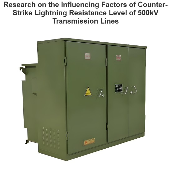
- Lightning Over - Voltage:Most of the high - and low - voltage lines of rural distribution transformers are overhead lines. The probability of being struck by lightning is relatively high in mountainous areas, forested areas, and plains. When the line is struck by lightning, an impulse voltage dozens of times higher than the rated voltage is generated on the windings of the distribution transformer. If the lightning arresters installed at the high - and low - voltage outlets of the distribution transformer cannot play an effective protective role or have certain hidden dangers themselves, such as the lightning arresters not being put into operation simultaneously, poor grounding of the lightning arresters, or excessive grounding resistance, it will be difficult to avoid damage to the distribution transformer caused by lightning strikes.
- Ferroresonance in the System:In a 10 kV power distribution system, there are many small - sized distribution transformers, electric welders, and speed - regulating machines. The equivalent inductance and capacitance of the system may be equal to or close to each other, leading to system resonance. During resonance, in addition to the sudden increase in the current of the distribution transformer and the fusing of the fuse, over - voltage will also be generated, causing the bushing of the distribution transformer to flashover or explode.
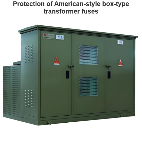
2.4.5 Improper Selection of Fuse Elements
Distribution transformers are usually protected by fuses. If the fusing current is selected too small, it is extremely easy to fuse under normal operating conditions, resulting in the interruption of power supply to users. If the fusing current is selected too large, it will not play a protective role. In rural distribution transformers, for various reasons, copper wires, aluminum wires, and iron wires are often used instead of fuse elements, so the distribution transformer cannot be effectively protected. In normal use, the selection criteria for fuse elements are as follows: for distribution transformers with a capacity of more than 100 kVA, the primary - side fuse element should be configured with a rated current 1.5 - 2.0 times the rated current of the transformer; for distribution transformers with a capacity of less than 100 kVA, the primary - side fuse element should be configured with a rated current 2.0 - 3.0 times the rated current of the transformer; the low - voltage - side fusing element should be selected according to 1.1 times the rated current.
2.4.6 Other Reasons
Since the primary and secondary leads of the distribution transformer are both copper screws, and the overhead lines generally use aluminum wires, ionization occurs at the copper - aluminum interface under the influence of external factors, forming an oxide film between copper and aluminum. The contact resistance increases, causing the copper screws, nuts, and leads at the lead - out to burn out.
During the maintenance or installation process, when tightening or loosening the nuts of the distribution transformer leads, the conductive screws rotate accordingly, resulting in disconnection of the primary - side coil leads or inter - phase short - circuit caused by the soft copper sheets of the secondary - side leads touching each other.
Parallel - operating distribution transformers are not phase - checked after maintenance, testing, or cable replacement. Random wiring leads to incorrect phase sequence. After the distribution transformers are put into operation, a large circulating current will be generated, burning the distribution transformers.
Since most lighting loads use single - phase power supply and the management is not in place, the distribution transformers often operate unbalanced in three phases for a long time, causing the insulation of a certain phase coil to age and burning the distribution transformers.
3. Preventive Measures
3.1 Pre - Commissioning Inspection
3.1 Pre - Commissioning Inspection
Before a distribution transformer is put into operation, on - site inspection must be carried out. The main contents are as follows:
- Check whether the oil - level gauge on the oil conservator is intact, and whether the oil level is clear and on the oil - level line corresponding to the ambient temperature.
- Check whether the cover plate, bushings, oil - level gauge, oil drain valve, etc. are well - sealed and whether there is any oil - leakage phenomenon.
- Check whether the explosion - proof membrane of the explosion - proof tube (safety air duct) is intact, and whether the moisture - absorbing agent of the breather has expired.
- Check whether the shell of the distribution transformer and the neutral - point grounding on the low - voltage side are firm and reliable, and whether the grounding resistance meets the requirements.
- Check whether the connection between the primary and secondary outlet bushings of the distribution transformer and the wires is good, and whether the phase colors are correct.
Measure the insulation resistance and DC resistance of the distribution transformer, which should comply with the relevant provisions of GB 50150 - 1991 Electrical Equipment Installation Engineering - Electrical Equipment Commissioning Test Standard.
If all the above inspections are qualified, first energize the distribution transformer without load, check whether there are any abnormal electromagnetic sounds, and measure whether the secondary - side voltage is balanced. If it is balanced, it indicates that the transformation ratio of the distribution transformer is normal, there is no inter - turn short - circuit, and the distribution transformer can operate with load normally.
3.2 Precautions during Operation
- Carefully check the environment around the distribution transformer rack (such as landslides, illegal buildings), and whether there are ultra - high trees. Check whether these trees can fall onto the distribution transformer under the influence of strong wind, etc., causing low - voltage or high - voltage short - circuit of the distribution transformer and burning it.
- Carefully check whether the pole of the distribution transformer rack is firm and whether there is a risk of the pole falling.
- Strengthen the inspection of low - voltage lines in the distribution area. Cut down ultra - high trees in the line corridor in time to prevent low - voltage line short - circuit faults.
- Carefully clean the low - voltage outlets of the distribution transformer. Replace or tidy up the damaged and messy 400V/220V low - voltage main lines to prevent low - voltage line short - circuit and disconnection faults.
- During the operation of the distribution transformer, regularly check whether the three - phase voltage and load are balanced. If there is a serious imbalance, take measures to adjust.
- Regularly check the oil color and oil level of the distribution transformer, and whether there is any oil leakage. Eliminate defects in time to prevent the tap - changer and windings from getting damp.
- Regularly clean the dirt and dust on the distribution transformer. Check whether there is any flashover discharge on the bushings, whether the grounding is good, and regularly telemeter the grounding resistance. (For distribution transformers with a total capacity of more than 100 kVA, the grounding resistance of the grounding device should not be greater than 4Ω, and the grounding resistance of each repeated grounding device should not be greater than 10Ω; for distribution transformers with a total capacity of 100 kVA or less, the grounding resistance of the grounding device should not be greater than 10Ω, and the grounding resistance of each repeated grounding device should not be greater than 30Ω, and there should be no less than 3 repeated groundings.)
- When installing or removing the leads of the distribution transformer, strictly follow the maintenance process to avoid internal breakage of the leads. Reasonably select the wiring method of the wires, such as using copper - aluminum transition clamps or wire plates. Apply conductive paste on the contact surface to increase the contact area and conductivity, and reduce oxidation and heating.
- According to the technical requirements of 10/0.4kV distribution transformers, install lightning arresters on the primary and secondary sides of the distribution transformer, and ground the grounding leads of the lightning arresters, the shell of the distribution transformer, and the neutral point of the secondary side respectively. Adhere to the annual preventive test, and replace unqualified lightning arresters in time to reduce the damage to distribution transformers caused by over - voltage due to lightning strikes and resonance. Actively promote the use of S11 series new - type lightning - proof and energy - saving distribution transformers.
- Install fuses or drop - out fuses on both sides of the distribution transformer, and configure appropriate fuse elements. The selection requirements for fuse elements are as follows: the rated current of the primary - side fuse element is selected according to the multiple of the rated current of the transformer. For transformers of 10 - 100 kV·A and below, it is 1 - 3 times; for transformers above 10 - 100 kV·A, it is 1.5 - 2 times; the rated current of the secondary - side fuse element is selected according to the secondary - rated current of the transformer; for a dedicated transformer for a single motor, considering the starting current, the rated current of the secondary - side fuse element can be selected as 1.3 times the rated current of the transformer.
- Before and after each adjustment of the no - load tap - changer, measure the DC resistance value twice, and make records. Compare whether the three - phase DC resistance is balanced (the inter - phase difference is not greater than 4%, and the line - to - line difference is not greater than 2%). Compare the changes in the three - phase DC resistance before and after adjustment, and the difference between the three - phase DC resistance and the historical value. Only after ensuring that the adjustment is normal and error - free can the transformer be put into use.
4. Conclusion
Most of the faults of distribution transformers are caused by inadequate management and improper operation and maintenance. First, strengthen equipment inspection and management. Timely remove trees, illegal buildings, and geological safety hazards around the low - voltage outlet rack and corridor. At the same time, eliminate defects in the transformer body in time. Second, do a good job in load forecasting and monitoring. Carefully analyze the load situation of the transformer to avoid over - load or serious three - phase unbalanced operation.
Third, do a good job in lightning protection measures. Timely detect the grounding resistance and replace unqualified lightning arresters or install lightning arresters. Fourth, install fuses or drop - out fuses on both sides of the distribution transformer and configure appropriate fuse elements. Fifth, strictly follow the regulations and maintenance process. Sixth, conduct on - site inspection of the distribution transformer before it is put into operation and ensure it is qualified. In this way, most of the faults such as burning of distribution transformers can be avoided.
Hey there! I'm an electrical engineer specializing in Failure and Maintenance. I've dedicated my career to ensuring the seamless operation of electrical systems. I excel at diagnosing complex electrical failures, from malfunctioning industrial motors to glitchy power distribution networks. Using state - of - the - art diagnostic tools and my in - depth knowledge, I pinpoint issues quickly. On this platform, I'm eager to share my insights, exchange ideas, and collaborate with fellow experts. Let's work together to enhance the reliability of electrical setups.