Protection of American-style box-type transformer fuses

Introduction to Fuses of American-style Box Transformers
American-style box transformers generally use a combination of plug-in fuses and backup protection fuses in series to provide protection. The protection principle is advanced and reliable, and the operation is simple. The backup protection fuse is an oil-immersed current-limiting fuse, usually installed inside the box transformer. It will operate only when a fault occurs inside the box transformer, and it is used to protect the high-voltage line. The plug-in fuse is an oil-immersed plug-in fuse, which will blow when a short-circuit fault occurs on the secondary side, or when there is an overload or the oil temperature is too high. The plug-in fuse is a main accessory for over-current protection of oil-immersed box transformers in the power distribution system.
The fuses inside can be classified into three types: current type, dual-sensitive type, and dual-factor type. The fuse can be withdrawn for replacement without powering off the box transformer. The current-type fuse, when connected in series with the backup protection fuse, forms a "double-fuse protection". The current-type fuse is used for overload protection, and the backup protection fuse is used to protect against internal faults of the transformer (such as coil short circuits, etc.). The dual-sensitive fuse, when connected in series with the backup protection fuse, also forms a "double-fuse protection". The dual-sensitive fuse protects against faults or overloads on the low-voltage side of the transformer in terms of both current and temperature.
The backup protection fuse is used to protect against internal faults of the transformer (such as coil short-circuit faults, etc.). The standard ampere-second curve can accurately cooperate with the fuses and circuit breakers at upper and lower levels. The dual-factor fuse, when connected in series with the backup protection fuse, constitutes "double-fuse protection". The dual-factor fuse protects against faults or overloads on the low-voltage side of the transformer from the aspects of both current and temperature. The backup protection fuse is used to protect against internal faults of the transformer (such as coil short-circuit faults, etc.), and its standard ampere-second curve can accurately cooperate with the fuses and circuit breakers at upper and lower levels.
Basic Structure of Fuses
Fuses have different structures according to the functions they perform. This article briefly introduces the McGraw Edison NX type current-limiting fuse of COOPER (Cooper) Company in the United States.
The McGraw Edison NX type current-limiting fuse structure is shown in Figure 1. It contains a fusible element with a pure silver fuse strip. The pure silver fuse strip is wound on a mica support (spider-type support component), and this support can generate ionized gas that helps to open the circuit. The fuse and silica sand are installed in a glass fiber insulation tube.
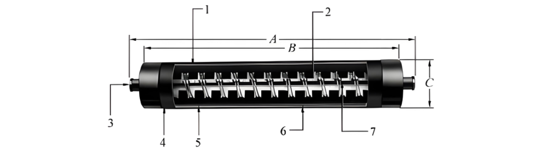
1 - High-purity silica sand filler;2 - Mica support;3 - Solid copper terminal;4 - Double-sealing system;5 - Identification label;6 - Glass fiber cover;7 - Pure silver fuse strip.
Figure 1. Basic constituent elements of the McGraw Edison NX type current-limiting fuse.
As shown in Figure 1, the McGraw Edison NX type current-limiting fuse (other fuse models have similar structures to this fuse) mainly includes:
- High-purity silica sand filler. The specific particle size, purity, and density provide heat absorption and arc extinguishing characteristics, which are essential for the fuse to maintain consistent clearing characteristics and a low energy passing level.
- Mica support. During the operation of the fuse, the mica support provides stable winding support without generating gas and pressure accumulation.
- Solid copper terminal. The brass plug is selected to provide an electrical conductive joint with a length ranging from 0.25 to 10 inches.
- Double-sealing system. The nitrile rubber gasket and epoxy resin sealant can ensure the integrity of the fuse seal.
- Firm identification label. It is convenient for users to obtain voltage, current parameters, order numbers, and other information.
- Glass fiber cover. It provides high strength for the fuse and the integrity of maintenance, enabling the fuse to withstand a protection range from the minimum fusing current to a maximum of 50 kA during any interruption process.
- Pure silver fuse strip. It can maintain stability under current circulation and thermal pressure conditions and provides consistent fusing characteristics. During the interruption of large currents, the fuse strip can effectively control and reduce the peak level of the arc voltage. During the interruption process, this component can effectively control and limit the allowable passing current and energy.
Operating Characteristics and Protection Principle of the Fuse
The working process of the fuse depends on the model of the fuse element inside it. For all fuses, the clearing of large fault currents is basically the same. The flow of current will melt the fusible element along its entire length, and the generated arc will cause the fusible element to explode, vitrifying the silica sand and forming a glassy channel that restricts the development of the arc. This glassy channel limits the arc by increasing the resistance value, reducing the current and forcing it to reach zero in advance.
In the local or full-range fuse, the clearing of the medium or small currents must be prevented. For example, in the McGraw Edison type current-limiting fuse, an "M" point (i.e., a tin alloy wire) is placed in the center of the main fusible element to lower its melting temperature, as shown in Figure 2(a). Once the fusible element melts at the M point, the current is transferred to the auxiliary fusible element. A thin wire is connected to the main fusible element with a 1/4 gap from one end of the main element. A voltage gradient spans the arc at the M point and the gap of the auxiliary fusible element, as shown in Figure 2(b). Therefore, if the main fusible element continues to arc, this wire connection will inevitably appear at three positions, expanding the length of the arc by three times and using this area to dissipate the energy of the circuit, as shown in Figure 2(c). In the initial stage of arcing, sufficient heat is gathered to decompose the spider structure in that area, and the gas blown out from the spider structure can cool the molten rock and reduce the length of the arc until the fault point can be disconnected.
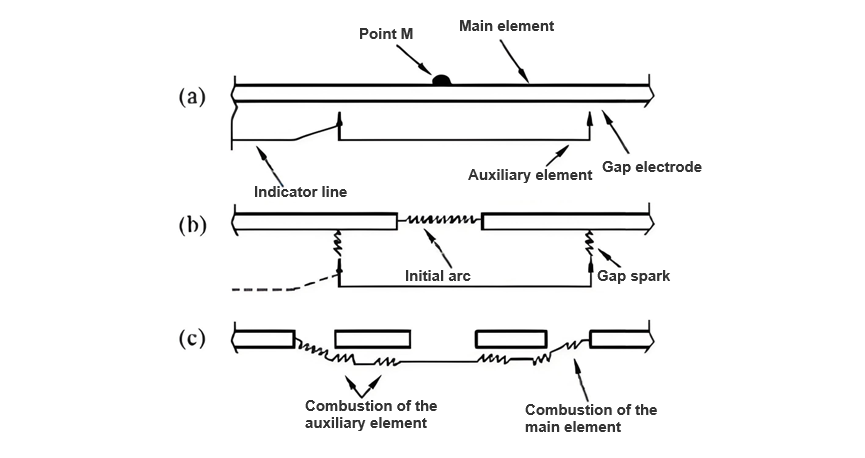
Figure 2 The process of the McGraw Edison NX type current-limiting fuse reducing the current
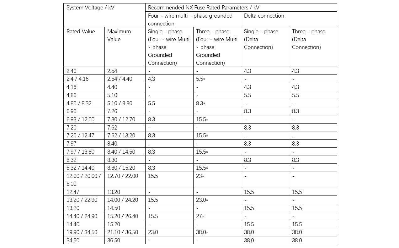
The selection of current-limiting fuses is primarily based on their rated voltage parameters. When determining the appropriate parameters, several factors need to be taken into account, including the type of electrical system, the maximum voltage of the system, the winding conditions of the transformer (if the fuse is used for transformer protection), the grounding status of the neutral wire, and the type of load.
Generally, a single-phase circuit can be protected by a current-limiting fuse with a rated parameter greater than the single-phase grounding voltage. However, for a three-phase circuit, the fuse must have suitable inter-phase parameters. In specific cases, assuming that the positive-sequence breaking voltage applied to the fuse does not exceed the maximum design voltage, the single-phase grounding parameters may be applicable to the three-phase system. Under such circumstances, it is assumed that two series-connected current-limiting fuses will share the applied voltage in the given fault condition. Table 1 illustrates the relationship between the recommended rated voltage parameters and the application parameters of current-limiting fuses.
For the protection of electrical devices, the breaking requirements of current-limiting fuses must be coordinated with the devices they protect. Additionally, the time-current curves of the fuses must also be coordinated with the protection devices in the system, especially when backup fuses are involved and the clearing of low-current faults relies on a expulsion fuse.
Table 1 Recommended Rated Voltage Parameters of Current-Limiting Fuses and the Application Parameters of Current-Limiting Fuses
Similar to ordinary fuses, current-limiting fuses may also experience a reduction in power under a certain ambient temperature. The derating factors for various application scenarios are shown in Figure 3.
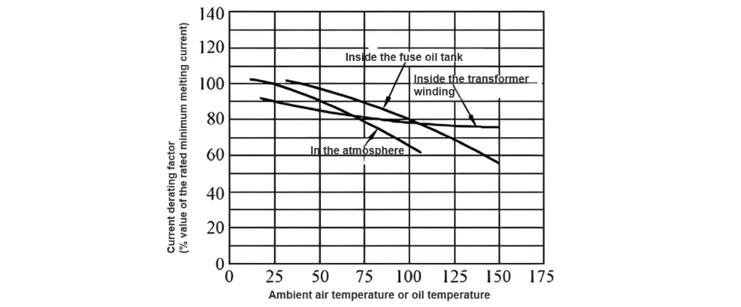
Figure 3 Ambient Temperature Derating Factors for Applications of NX - type Current - Limiting Fuses
The key to applying fuse protection for distribution transformers is that the fuse must meet the following requirements:
- Provide short-circuit protection and separate the faulty transformer from the system first. The fuse should not blow during inrush current, cold load starting current, and short-term overcurrent. It should cooperate with the upper-level device (blow before the sectionalizer operates).
- Prevent severe overcurrent situations that may cause overheating damage or mechanical damage to the transformer. It should be noted that if necessary, item ② can be postponed because the primary purpose of fuse protection is overload protection rather than short-circuit protection.
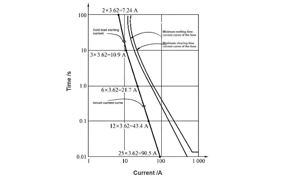
The time-current curve of the inrush current/cold load starting current of the distribution transformer is estimated based on the following situations: at 0.01 s, the current is 25 times the full-load current; at 0.1 s, the current is 12 times the full-load current; at 1 s, the current is 6 times the full-load current; at 10 s, the current is 3 times the full-load current; and at 100 s, the current is 2 times the full-load current.
To ensure that the fuse used for the protection of the distribution transformer does not blow during inrush current or cold load starting current, the fuse curve should be on the right side of the inrush current/cold load starting current curve. That is to say, the blowing time of the fuse should be longer than the duration of these currents.
The transformer damage curve can be obtained from the manufacturer or the ANSIC57 standard and can be plotted on the same curve graph. As mentioned before, if concessions need to be made, the transformer damage curve should be prioritized over the inrush current curve.
Figure 4 shows the inrush current/cold load starting current curve of a single-phase transformer with a voltage level of 13.8 kV and a rated capacity of 50 kV·A. The full-load current of the transformer is 3.62 A. A fuse curve is assumed in the figure. In fact, there are two fuse curves. The minimum melting curve gives the shortest time for the fuse to be damaged, and the maximum clearing curve gives the longest time for the fuse to clear the fault. The maximum clearing time of the expulsion fuse should never be lower than 0.8 cycles (i.e., 0.0133 s), so this curve is horizontally plotted at 0.0133 s.
In addition, when selecting a fuse for the protection of a box transformer, the coordination between fuses must also be considered. Here, the coordination issues in two situations are discussed:
- Coordination between two current-limiting fuses. To achieve the coordination objective, the curve must start from 0.01 s. For times above 0.01 s, the coordination between two different fuses in the same set can be achieved by simply overlaying the TCCS and using the 75% coordination method; for times below 0.01 s, the coordination can be achieved by using the minimum melting and total clearing values. When two current-limiting fuses are coordinated in series, the maximum current passing through the protection fuse or the load-side fuse should not exceed the minimum melting current of the protected or power-source-side fuse. That is, the load-side fuse will limit the passing current to a level that is not sufficient to melt the power-source-side fuse. Coordination detection above 0.01 s is not required because the coordination boundaries have fixed values. The coordination is conservative and forms a coordination standard for any fault current. If the fault current is limited, the coordination can be achieved by changing the current in the curve.
- Coordination between the backup current-limiting fuse and the expulsion fuse. This protection method is often adopted because it allows most faults (under small currents) to be cleared by an inexpensive expulsion fuse. When a fault occurs in the protected device, the current-limiting fuse will limit the magnitude of the current. It is very important that the expulsion fuse can clear small current faults without damaging the current-limiting fuse. The current-limiting fuse can pass sufficient current after the expulsion fuse is blown and can provide obvious fault indication. The fuse characteristics will form the intersection of the maximum clearing curve of the expulsion fuse and the minimum fusing curve of the current-limiting fuse, resulting in a larger current, which will lead to synchronous operation. If the two current-limiting fuses are properly selected, the box transformer can achieve full-range protection.
- The plug-in fuse is manually operated, and users need certain skills and experience. Before using the plug-in fuse to disconnect the energized transformer, the operator should have experience in removing the plug-in fuse from the fuse holder. Improper handling may lead to switching faults and may require the replacement of the transformer or cause a fire.
- If the plug-in fuse is used for fault closing, it may cause serious personal injury. Internal faults may cause the transformer to crack or the top cover to detach. Therefore, the transformer should always be powered from a remote location to ensure safety.
- (3) If the transformer is located in an enclosed building or cellar, or if the operator is directly above the transformer, the plug-in fuse assembly should not be used to connect or disconnect the transformer. In such situations, it is inconvenient for the operator to operate correctly, and it is difficult to leave safely in case of improper operation.
- Before operating the plug-in fuse, the status of the transformer should be carefully judged. Check whether there is an arc discharge sound in the casing; check whether the casing is bulged or there are traces of oil leakage or overflow; check whether there are traces of oil leakage, overflow, or carbon black stains on the casing near the pressure relief device. If the above situations occur, the plug-in fuse should not be used to connect or disconnect the transformer, otherwise, it may lead to a fire or cause casualties.
- The pressure of the transformer should be released before operating the plug-in fuse. Incorrectly discharging the pressure of the transformer casing may cause the insertion assembly of the plug-in fuse to be violently ejected together with the hot oil. This may cause impact injuries, burns, and environmental pollution.
- Using a plug-in fuse with an excessively high ampere value may lead to a mismatch with the backup current-limiting fuse in the transformer or other parts of the system. In this case, when a fault occurs inside the transformer, it may cause a larger power outage or lead to the ignition or explosion of the transformer. Installing a plug-in fuse with an ampere value smaller than the recommended value will cause unnecessary fusing and interruptions in operation.
- Damage to the fuse tube will affect the correct installation of the fuse. Carefully check the fuse tube to ensure that there is no corrosion larger than pitting on any part of the brass, and that the blackening or ablation of the insulating components is not longer than 1/2 in (13 mm). If the damage exceeds this degree, the damaged fuse tube should be replaced with a new one. If a large amount of brass melting occurs, or the ablation extends beyond half of the length of the fuse tube, the plug-in fuse holder should also be replaced. If the component is damaged, it may prevent the disconnection of subsequent faults and cause greater damage.
Conclusion
The technical level of fuse protection is relatively advanced, and it has an excellent performance-price ratio, with broad development prospects in both domestic and foreign markets. Currently, a large number of American-style box transformers in China use fuses for protection. Compared with other protection methods, fuse protection not only has high reliability but also a relatively low price, which is particularly suitable for the current situation in China. Therefore, fuse protection has good application prospects in China.
Hey there! I'm an electrical engineer specializing in Failure and Maintenance. I've dedicated my career to ensuring the seamless operation of electrical systems. I excel at diagnosing complex electrical failures, from malfunctioning industrial motors to glitchy power distribution networks. Using state - of - the - art diagnostic tools and my in - depth knowledge, I pinpoint issues quickly. On this platform, I'm eager to share my insights, exchange ideas, and collaborate with fellow experts. Let's work together to enhance the reliability of electrical setups.