Failure Analysis and Troubleshooting Cases of Distribution Transformers

Fault Causes of Distribution Transformers
Faults Caused by Temperature Rise
Impact on Metal Materials
When a transformer is in operation, if the current is too large, causing the customer load to exceed the rated capacity of the transformer, the temperature of the transformer will rise, which in turn softens the metal materials and significantly reduces their mechanical strength. Take copper as an example. If it is exposed to a high - temperature environment above 200 °C for a long time, its mechanical strength will be significantly weakened; if the temperature exceeds 300 °C in a short time, the mechanical strength will also drop sharply. For aluminum materials, the long - term working temperature should be controlled below 90 °C, and the short - term working temperature should not exceed 120 °C.
Impact of Poor Contact
Poor contact is an important cause of many distribution equipment failures, and the temperature of the electrical contact part has a great impact on the quality of electrical contact. When the temperature is too high, the surface of the electrical contact conductor will oxidize violently, and the contact resistance will increase significantly, causing the temperature of the conductor and its components to rise, and in severe cases, the contacts may be welded together.
Impact on Insulation Materials
When the ambient temperature exceeds the reasonable range, organic insulation materials will become brittle, accelerating their aging process, leading to a significant decline in insulation properties, and in severe cases, dielectric breakdown may occur. Studies have shown that for Class A insulation materials, within their temperature - resistant range, for every 8 - 10 °C increase in temperature, the effective service life of the material will be reduced by nearly half. This relationship between temperature and service life is known as the "thermal aging effect", which is an important factor affecting the reliability of insulation materials.
Faults of Distribution Transformers Caused by Poor Contact
Faults Caused by Oxidation of Protective Coatings
In order to improve the comprehensive performance of conductive components, surface modification technologies are often used in engineering practice to treat key contact parts. Take the conductive rod of a transformer as an example. A precious metal protective layer (such as gold, silver, or tin - based alloy) is usually formed on its working surface through electroplating. This metallurgical bonding layer can significantly improve the physical and chemical properties of the contact interface.
It should be noted that during the mechanical operation in equipment maintenance or under long - term thermal load, the coating may partially peel off or suffer from oxidation and corrosion, thereby causing problems such as abnormal increase in contact resistance and decrease in current - carrying capacity. Experimental data shows that when the thickness loss of the coating exceeds 30%, the electrical conductivity stability of its interface will show an exponential decay trend.
Chemical Corrosion Caused by Direct Connection of Copper and Aluminum
In an electrical connection system, the direct contact between copper and aluminum dissimilar metals will form a significant electrode potential difference, and its potential value can reach 0.6 - 0.7 V. This potential difference will trigger serious galvanic corrosion. In engineering practice, due to non - compliance with construction specifications or improper material selection, the direct connection of copper and aluminum conductors without transition treatment occurs frequently.
After this connection method is energized, an oxide film layer will gradually form at the contact interface, resulting in a non - linear increase in contact resistance. Under the rated working temperature, the effective service life of such joints is usually no more than 2000 hours, and finally, failures will occur due to the deterioration of the contact surface.
Severe Heating at Electrical Contacts Caused by Poor Contact
During the actual installation of distribution transformers, anti - theft metering boxes are usually configured on the low - voltage side. Due to the limited internal space of the metering box and non - standard construction techniques, problems such as winding connection of wires or loose mechanical crimping of terminal blocks often occur. These poor connections will lead to an abnormal increase in contact resistance, causing overheating under the action of load current, and then triggering the ablation failure of the low - voltage conductive rod.
More seriously, the continuous temperature rise at the end of the low - voltage winding will accelerate the thermal aging process of the insulation material, creating hidden dangers of partial discharge. At the same time, overheating will also cause the transformer oil to undergo a pyrolysis reaction, reducing its insulation strength and cooling performance. Experimental data shows that when the oil temperature continuously exceeds 85 °C, its breakdown voltage will decrease by about 15% - 20% per year. This multiple deterioration effect is very likely to cause insulation breakdown accidents when encountering lightning overvoltage or switching overvoltage, ultimately leading to the failure of the transformer.
Faults of Distribution Transformers Caused by Humidity
The increase in ambient relative humidity has a dual impact on the insulation system of distribution equipment. Firstly, the dielectric strength of humid air decreases significantly, and its breakdown field strength is negatively correlated with humidity; secondly, the adsorption of water molecules on the surface of insulation materials will form conductive channels, resulting in a decrease in surface resistivity. More seriously, when moisture diffuses into the interior of solid insulation media or dissolves in transformer oil, it will cause a sharp increase in dielectric loss.
When the water content in transformer oil reaches about 100 μL/L, its power - frequency breakdown voltage will drop to about 12.5% of the initial value. This deterioration of insulation performance will significantly increase the leakage current of the equipment. In a humid environment, partial discharge may occur even under the rated operating voltage. Statistical data shows that in an environment with a relative humidity exceeding 85%, the failure rate of distribution transformers increases by 3 - 5 times compared with that in a dry environment, mainly manifested as insulation breakdown and surface flashover accidents.
Faults of Distribution Transformers Caused by Improper Installation of Lightning Arresters
In the power system, the performance reliability of overvoltage protection devices directly affects the operation safety of transformers. As the main protection components, the installation quality, operation and maintenance, and preventive tests of metal oxide arresters (MOA) are the key links to ensure their effectiveness. However, due to non - standard construction techniques, inadequate implementation of detection procedures, and the lack of professional literacy of operation and maintenance personnel, the actual protection effect of the protection devices is often greatly reduced, which is an important cause of insulation breakdown accidents of distribution transformers.
From the perspective of operation practice, protection devices will be affected by various environmental stresses during long - term service. Factors such as temperature cycles, mechanical vibrations, and corrosive media may cause the degradation of the connection performance of the grounding system. When the system is subjected to lightning strikes, the failed grounding loop will not be able to discharge the overvoltage energy in time, resulting in thermal breakdown of the protection device itself. According to statistics, among the fault cases of protection devices, explosion accidents caused by poor grounding account for more than 60%, and the energy release process is often accompanied by intense arc discharge.
Several Fault Diagnosis Methods for Distribution Transformers
Fault Diagnosis through Intuitive Judgment
The fault diagnosis of distribution transformers can be initially judged through external characteristics. The observation contents include: the integrity of the casing (cracks, deformation), mechanical status (loose fasteners), sealing performance (leakage traces), surface condition (dirt level, corrosion phenomena), and abnormal signs (color changes, discharge marks, smoke generation), etc. These external characteristics have specific corresponding relationships with internal faults .
When the transformer oil shows a dark brown color and has a burnt smell, accompanied by abnormal temperature rise and the operation of high - voltage - side protection components, it usually indicates that there are abnormalities in the magnetic circuit system, possibly insulation damage between silicon steel sheets or multi - point grounding faults of the magnetic conductor.
If the operating current increases abnormally, the oil temperature rises significantly, the three - phase parameters are asymmetrical, accompanied by the operation of low - voltage - side protection devices, smoke in the oil conservator, and fluctuations in the secondary voltage, it can be determined as a turn - to - turn short - circuit fault caused by the failure of the insulation between winding conductors. When the electrical parameters of a certain phase completely disappear (voltage and current are 0), this feature usually corresponds to a winding open - circuit or connection conductor fusing fault.
The oil spraying phenomenon of the oil conservator is an important sign of serious internal faults of the transformer. When the gas generation rate of the fault exceeds the processing capacity of the pressure relief device, positive pressure will be formed inside the oil tank. Initially, it is manifested as leakage at the weak sealing points. As the pressure continues to rise, oil spraying may finally occur at the joint surface of the tank body. This kind of fault is mostly caused by inter - phase insulation breakdown of the winding, usually accompanied by the fusing of high - voltage - side protection components. According to the statistics of gas relay actions, about 75% of serious faults will go through this development process.
Fault Diagnosis through Temperature Changes
During the operation of distribution transformers, the current - carrying conductors will inevitably generate heat losses due to the Joule effect, which is a normal physical phenomenon. However, when the equipment has electrical abnormalities (such as insulation degradation, poor contact) or mechanical defects (such as winding deformation, cooling system failure), its thermal equilibrium state will be disrupted, manifested as the operating temperature exceeding the designed allowable value. According to the thermal aging theory, for every 6 - 8 °C increase in temperature, the aging rate of insulation materials will double, thus significantly affecting the service life of the equipment.
For abnormal temperature rises caused by internal faults, there are usually obvious abnormalities in the oil circuit system. When the hot - spot temperature reaches the critical value, the transformer oil will undergo a pyrolysis reaction, generating a large amount of gas, causing the pressure relief device to operate, resulting in oil leakage or oil spraying. In engineering practice, a simple method can be used to initially judge the temperature status of the equipment: if the surface of the transformer casing can be touched by hand for more than 10 seconds, its surface temperature usually does not exceed 60 °C. This empirical value can be used as a reference for on - site rapid assessment.
Fault Diagnosis through Odor Changes
The moment the cover of the oil pillow is opened, a peculiar pungent burnt smell can be smelled. This indicates that the coil inside the transformer is burned, often accompanied by the fusing of two to three - phase drop - out fuses.
Fault Diagnosis through Sound Changes
During the operation of a transformer, the magnetostriction effect generated by the magnetization of the iron core will trigger periodic mechanical vibrations. These vibrations and their accompanying acoustic characteristics serve as important indicators of the normal operation of the equipment. Acoustic diagnosis technology enables effective monitoring of the operating status of the transformer. Specifically, the frequency characteristics of the sound signal, changes in the sound pressure level, and the vibration spectrum characteristics can reveal potential faults of the equipment.
When using the acoustic detection method, a conductive rod (such as an insulating rod) can be employed as a medium for sound wave conduction. One end of the rod is brought into contact with the equipment's outer shell, and the other end is placed close to the auditory organ for listening. Once abnormal sound signals are detected, preventive maintenance measures should be promptly implemented to prevent the escalation of faults. The following are the correspondences between typical acoustic characteristics and fault types:
- Intermittent "clicking" sounds: Usually, this indicates that the iron core laminations are loose or that the fasteners have insufficient torque. The sound pressure level generally falls within the range of 60 to 70 decibels.
High-frequency discharge sounds: Accompanying partial discharge phenomena, the sound signals exhibit a "cracking" characteristic. In severe cases, the sound pressure level can exceed 85 decibels, and visible discharge marks are often present. - Sudden explosive sounds: These mostly occur when the insulation of the leads is damaged or there is a discharge to the ground. The sudden change in the sound pressure level exceeds 20 decibels.
- Low-frequency rumbling sounds: Commonly associated with low-voltage side grounding faults, the frequency of the sound signals is concentrated within the range of 100 to 400 hertz.
- Sharp whistling sounds: This indicates that the equipment is in an over-excitation state, and the main frequency of the sound signals is typically between 1 and 2 kilohertz.
- Bubble boiling sounds: Accompanying abnormal increases in the oil temperature, the sound signals display a continuous "gurgling" characteristic, usually indicating the deterioration of the oil insulation performance.
Fault Diagnosis through Instruments
Due to the constraints of equipment technology, power supply stations mostly use a multimeter to measure whether the resistance of the winding conductors is conducting to determine whether there are broken wires or turn - to - turn short - circuits inside the transformer; an insulation resistance tester is used to measure the insulation resistance of each winding of the transformer to the ground, so as to determine whether the main insulation is broken down. When the insulation between the winding and the ground or between phases is broken down, its insulation impedance value will approach 0 Ω.
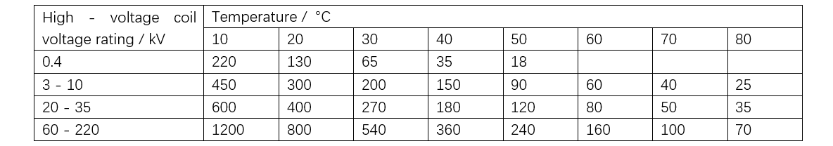
When testing the insulation performance of the winding, the insulation parameters of the following three circuits need to be measured respectively: the insulation resistance between the primary winding, the secondary winding, and the casing; the insulation resistance between the secondary winding, the primary winding, and the casing; and the insulation resistance between the primary winding and the secondary winding. It should be noted that the reference ground potential point in the test is the metal casing structure of the transformer. The reference values of the insulation resistance of oil - immersed transformers are shown in Table 1.
Fault Diagnosis Technologies for Distribution Transformers
Fault diagnosis technologies for distribution transformers are crucial means to ensure the safe operation of equipment. Through advanced diagnosis technologies, potential faults can be detected in a timely manner, and effective measures can be taken to prevent the expansion of faults. The following introduces several commonly - used fault diagnosis technologies for distribution transformers.
Winding DC Resistance Test
The winding DC resistance test is one of the basic methods for detecting the health status of transformer windings. By measuring the DC resistance of the winding, it is possible to determine whether there are problems such as broken wires, poor contact, or turn - to - turn short - circuits in the winding. For example, during routine inspection of a transformer in a certain area, an abnormal DC resistance of the high - voltage side winding was detected. Further inspection revealed a turn - to - turn short - circuit in the winding. Timely replacement of the winding avoided the occurrence of a more serious fault. The winding DC resistance test has the advantages of simple operation and intuitive results, and it is an indispensable detection method in the daily maintenance of transformers.
Dissolved Gas Analysis (DGA)
Dissolved Gas Analysis (DGA) is an important technical means for diagnosing internal faults of transformers. By analyzing the components and contents of gases dissolved in the transformer oil, it is possible to determine whether there are faults such as overheating and discharge inside the transformer. Using the IEC60599 three - ratio method, discharge - type faults can be accurately identified. For example, high concentrations of acetylene (C2H2) and hydrogen (H2) were detected in the oil of a certain transformer. Analysis by the three - ratio method determined it to be a discharge - type fault. Timely maintenance avoided equipment damage. DGA has the advantages of high sensitivity and accurate diagnosis, and it is an important means for monitoring the condition of transformers.
Partial Discharge Detection
Partial discharge detection is an important method for evaluating the insulation condition of transformers. Partial discharge usually occurs in weak insulation areas, and long - term discharge will lead to the gradual deterioration of insulation materials, ultimately causing serious faults. Through partial discharge detection, insulation defects can be detected in a timely manner, and preventive measures can be taken. For example, during partial discharge detection of a certain transformer, a discharge phenomenon was found in the high - voltage bushing. After replacing the bushing, the discharge phenomenon disappeared, effectively extending the service life of the equipment. Partial discharge detection has the advantages of non - destructiveness and high sensitivity, and it is an important means for monitoring the insulation of transformers.
Combined Vibration and Acoustic Detection
Combined vibration and acoustic detection is to determine whether there are mechanical faults inside the equipment by analyzing the vibration and sound signals during the operation of the transformer. For example, for a faulty transformer, the vibration amplitude exceeded the standard by 3 dB in the 125 Hz frequency band. Inspection revealed that the iron core clamp was loose. After timely tightening, the vibration returned to normal. Combined vibration and acoustic detection has the advantages of real - time monitoring and accurate diagnosis, and it is an important means for diagnosing mechanical faults of transformers.
Infrared Thermography Detection
Infrared thermography detection is to determine whether there are overheating faults in the equipment by detecting the temperature distribution on the surface of the transformer. For example, during infrared thermography detection of a certain transformer, an abnormal temperature was found at the connection of the high - voltage bushing. Inspection revealed that the connection bolts were loose. After timely tightening, the temperature returned to normal. Infrared thermography detection has the advantages of non - contact and rapid diagnosis, and it is an important means for diagnosing overheating faults of transformers.
Fault Elimination Methods and Examples for Distribution Transformers
Line Tripping Caused by Turn - to - Turn Short - Circuit in Transformer
Fault Phenomenon
An over - current trip occurred on a 10 kV line in a certain substation. After reducing part of the load, over - current still occurred during the trial re - closing.
Fault Cause Analysis
After the on - site maintenance personnel arrived at the fault area, they first used a megohmmeter to test the insulation performance of the power supply line, and the measured insulation value to the ground was about 2 MΩ. Subsequently, a monitoring instrument was connected to the open - delta terminal of the secondary side of the 10 kV voltage transformer. During the temporary energization test, the voltage reading was observed to be about 40 V. Combining the on - site investigation results, no new electrical equipment was connected to this line before the fault occurred.
Based on this, the possibility of over - current protection action caused by overload was excluded. According to the analysis of normal operating parameters, this line should neither trigger over - current protection nor have a single - phase grounding anomaly. Through systematic detection and comprehensive judgment, it was initially determined that the root cause of the fault might be the turn - to - turn insulation breakdown in the internal winding of a certain distribution transformer. After analysis, it was possible that there was a turn - to - turn short - circuit fault in a certain distribution transformer of this line. Therefore, the line was transferred from operation to maintenance, and the line inspection was notified.
Further inspection revealed that there was a turn - to - turn short - circuit in phase A of the high - voltage side of a 250 kV·A distribution transformer of a customer on this line, which was the real cause of the trip. The following analyzes the over - current and false grounding situations caused by the turn - to - turn short - circuit of this distribution transformer. Because of the turn - to - turn short - circuit inside the distribution transformer, the simplified equivalent circuit is shown in Figure 1.
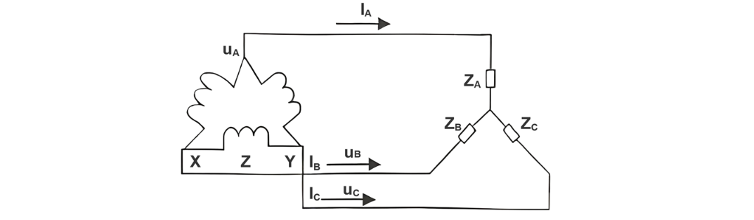
Let ZA, ZB, and ZC be the impedances of phases A, B, and C of the distribution transformer respectively. UO is the neutral point potential. When the three-phase load is balanced, UO = 0; when the three-phase load is unbalanced, UO≠0, resulting in neutral point displacement. When there is a phase-to-phase short circuit in phase A of the distribution transformer, the value of impedance ZA will decrease, and the value of IA will increase. When the sum of IA and the currents of phase A of other distribution transformers on this line is greater than the over-current operating value Idz of the relay protection, an over-current trip will occur. When there is a turn-to-turn short circuit in a certain transformer on phase A of the line, the impedance ZA of phase A of this transformer will decrease, and the voltage on the open delta side of the TV will rise. When this voltage exceeds the setting value of the relay, the central signal in the control room will send out a 10 kV grounding signal.
Accidents Caused by the Contact between the Low-Voltage Wire of the Transformer and its Shell
Fault Phenomenon
A 10 kV/400 V, 100 kV・A transformer in a certain unit supplies power to the load through two circuits on the low-voltage side. Since there is no power consumption load in one of the feeder circuits on the low-voltage side, it is decided to remove this line. After the wire removal work is completed, the power supply is restored. When the high-voltage drop-out fuses of phase A and phase C are closed, there is no abnormal phenomenon. However, when the drop-out fuse of phase B is closed, a huge arc suddenly occurs about 15 cm above the upper cover of the transformer, and then the transformer oil is ejected.
Fault Cause Analysis
After the accident occurs, a comprehensive understanding of the wire removal work is carried out, and a core lifting inspection of the transformer is conducted. During the inspection, it is found that the lead wire on the low-voltage side of phase B directly touches the shell, and there is a hole with a diameter of 1 cm at the contact point. The cause of the accident is that during the wire removal on the low-voltage side, the construction personnel accidentally rotate the screw of the low-voltage terminal of the transformer without noticing, resulting in the lead wire of phase B touching the shell of the transformer. Both the neutral point and the shell of this transformer are directly grounded, so the contact point between the lead wire of phase B and the shell becomes a grounding short-circuit point.
Treatment Countermeasures
First, the hole in the transformer body is repaired by welding. Then, the screw of the low-voltage lead wire connection is tightened. After that, the transformer oil is filtered, and the oil level is replenished to the safe level. After passing the test, the power supply is restored. In order to prevent such accidents, during the connection and disconnection of the transformer, the rotation of the connection screw should be avoided as much as possible. Once the screw rotates, strict treatment must be carried out. Only after confirming that there is no error can the transformer be put into use.
Faults Caused by the Blockage of the Transformer Breather Hole
Fault Phenomenon
A 315 kV·A distribution transformer newly installed in a certain farm stops running after a loud noise similar to thunder occurs. This happens one month after its commissioning.
Fault Cause Analysis
The power load at that time is investigated, which is 150 kW in total for the pumping water pump and the air compressor. Obviously, this transformer is operating under medium to light load, and the failure caused by overloading can be basically excluded. Through visual inspection, it is found that the two-phase fusing device is in an abnormal separation state. By tactile perception, it is found that the outer shell of the equipment is abnormally hot. At the same time, signs of insulation oil leakage on the main body are observed. A digital multi-functional detector is used to detect the resistance value of the winding, and the data shows that the windings of phases A/B/C on the high-voltage side are in an open-circuit state, while the electrical parameters of the low-voltage winding meet the standards. When the sealing component of the oil conservator is removed, an obvious gas escape sound is immediately generated.
This physical phenomenon indicates that abnormal gas pressure accumulates inside the equipment. At the same time, a characteristic smell of overheated insulation materials is detected. Based on the above characteristics, it is preliminarily determined that there is a thermal fault risk in the equipment. Subsequent disassembly and detection of the core components confirm that an insulation failure occurs in phases A and B of the high-voltage winding, leading to a coil burnout accident.
Why does this transformer burn out under light load? Through detection and analysis, it is found that the breather component preset at the bottom of the oil conservator of this equipment is not in use. Instead, a metal sealing plate is used for sealing treatment through fastening bolts, resulting in the accumulation of gas inside the equipment and the inability to achieve pressure balance. Under normal operating conditions, the insulation medium inside the transformer (liquid insulation oil and solid insulation materials) will gradually deteriorate due to the electrothermal effect, accompanied by the generation of trace amounts of hydrocarbon compounds and gaseous products such as CO and CO₂.
These gases, after being dissolved in the oil, diffuse dynamically inside the equipment following the concentration gradient. When there is abnormal temperature rise or partial discharge inside the equipment, the thermal decomposition reaction of the insulation materials is triggered. At this time, the gas generation rate, the total amount of gas, and the component characteristics are significantly correlated with the fault mode and its development degree. The thermal decomposition gas achieves a dynamic dissolution balance through the convection and diffusion of the oil. When the gaseous products exceed the saturation solubility of the oil, the excessive gas accumulates in the space above the oil surface.
Under normal circumstances, the pressure balance and gas discharge should be achieved through the breather. In this case, due to the complete blockage of the breathing channel, even when the equipment is operating under low load, the continuously generated heat, superimposed with the high ambient temperature, triggers multiple effects: the thermal expansion of the insulation oil leads to an abnormal increase in the pressure of the tank body, the oil circuit circulation is blocked, resulting in the failure of heat dissipation, and the temperature rise of the iron core and the winding exceeds the critical value, ultimately causing a turn-to-turn insulation breakdown accident.
Through thermodynamic simulation and disassembly verification, it is confirmed that the thermal aging process of the winding insulation system under this operating condition is accelerated by 8 to 12 times compared with the normal operating condition.
Oil Leakage from the Low-Voltage Bushing of the Transformer
Fault Phenomenon
During a routine safety inspection of a 315 kV·A distribution transformer in a certain food processing factory, oil leakage from the low-voltage bushing is found, and the factory is ordered to stop production and switch to maintenance.
Fault Cause Analysis
During the maintenance, it is found that the oil leakage occurs in phases B and C. The lap joints between the external copper busbars and the bushings of the distribution transformer are uneven, and there is a thick oxide layer on the surface. The copper busbars near the bushings show signs of discoloration due to high temperature. The compression nut of the conductive rod is welded to the conductive rod. Based on the above phenomena, the reason for the oil leakage from the bushings of phases B and C is that the lap joints between the copper busbars of these two phases and the bushings are improperly treated, resulting in a too large contact resistance. When a certain value of load current passes through, the temperature of the conductive rod in the bushing rises rapidly, causing the aging of the sealing rubber gaskets and rubber beads on the bushing, thus losing their elasticity and leading to oil leakage. In severe cases, welding occurs.
Treatment Countermeasures
First, carefully saw off the welded nut on the conductive rod with a fine hacksaw (pay attention not to damage the thread of the conductive rod) and remove the copper busbar. Then, saw off the heated part of the contact surface between the copper busbar and the low-voltage bushing, which is 20 cm. Next, select a 240 m² flexible copper wire as the transition wire. One end of the wire is connected to the copper busbar, and the other end is connected to the low-voltage conductive rod, making it less likely for the lap joint surface to deform and generate heat. At the same time, replace the sealing rubber gaskets and rubber beads. After the distribution transformer is put back into use, the situation is normal, and no overheating phenomenon is found.
Fuse Fusing Fault of Parallel-Operating Transformers
Fault Phenomenon
In a certain farm, there is a 100 kV·A distribution transformer and a 160 kV·A distribution transformer operating in parallel. After the maintenance and power restoration in the morning on the day of the fault, it is found that the phase A meter in the metering device of the 160 kV·A distribution transformer does not rotate. At noon, it is found that the 100 kV·A distribution transformer heats up, smokes, and leaks oil.
Fault Cause Analysis
This phenomenon first raises the suspicion of faults caused by changes in the parallel operation conditions of the transformers. There are four conditions for the parallel operation of transformers: the voltage ratios of the parallel transformers are equal (the ratio difference should not exceed 0.5%); the percentage of impedance voltage is equal; the winding groups are the same; the capacity ratio does not exceed 3:1. The on-site investigation shows that the load current per phase is between 200 and 240 A at that time.
The phase A meter of the metering device of the 160 kV·A distribution transformer stops running, and the rotation speeds of phases B and C are normal; the rotation speed of the phase A meter of the metering device of the 100 kV·A distribution transformer is significantly faster, and the rotation speeds of phases B and C are normal. Since these two transformers have been operating in parallel for a certain period, combined with the above phenomena, the distribution transformer accident caused by the circulating current due to non-compliance with the parallel operation conditions of the transformers can be basically excluded. Since the staff found that the 160 kV·A transformer stops running and the 100 kV·A transformer rotates very fast on-site, it is suspected that the distribution transformer accident is caused by the phase loss of the 160 kV·A distribution transformer.
By checking the high-voltage fuses of the 160 kV·A transformer, it is found that the high-voltage fuse of phase A is mechanically broken inside the fuse tube due to external tension. The real cause of this accident is that due to the phase loss of phase A of the 160 kV·A distribution transformer, the load of phase A of the whole field is pressed onto the 100 kV·A distribution transformer. The fuses of the 100 kV·A distribution transformer are not of the proper specification. The high-voltage fuse with a rated current value of 20 A fails to effectively blow during overloading, resulting in the heating and oil spraying of this distribution transformer during loaded operation.
Treatment Countermeasures
After replacing the fuse of the 160 kV·A transformer and reducing the load for operation, the situation is normal, and the metering device operates normally. The 100 kV·A distribution transformer is taken out of operation. After cooling, its insulation resistance is detected, and no abnormal phenomenon is found. When it is put into use, the situation is normal.
Experience and Lessons
The main reason for this accident is that the construction personnel fail to find the unreasonable fuse ratio during the maintenance, and the 100 kV·A distribution transformer fails to effectively blow during overloading. After being put into operation, the operation status of the distribution transformer is not checked in a timely manner, resulting in the phase loss operation of the 160 kV·A distribution transformer. In future work, comprehensive inspections must be carried out strictly in accordance with relevant regulations and technical requirements. Only when it is confirmed that the operation conditions are met can the equipment be put into use. After being put into use, tests should be carried out immediately to detect problems in a timely manner and eliminate potential accident hazards.
Preventive Maintenance Strategies for Distribution Transformer Faults
The preventive maintenance strategies for distribution transformer faults are the key to ensuring the long-term stable operation of the equipment. Through scientific maintenance strategies, the failure rate can be effectively reduced, the service life of the equipment can be extended, and the reliability of the power grid operation can be improved. The following introduces several effective preventive maintenance strategies.
Establish an Internet of Things (IoT)-Based Intelligent Monitoring System
Establishing an IoT-based intelligent monitoring system is an important means to realize the condition monitoring of distribution transformers. By installing sensors and data acquisition devices, the operation status of the transformer can be monitored in real time, and potential faults can be detected in a timely manner. For example, a certain power supply company establishes an intelligent monitoring system, which can realize the real-time monitoring of parameters such as the oil temperature, load, and vibration of the transformer. The accuracy rate of fault early warning reaches more than 90%. The intelligent monitoring system has the advantages of strong real-time performance and wide coverage, and it is an important tool for preventive maintenance.
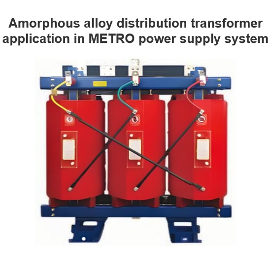
Promote Amorphous Alloy Core Transformers
Amorphous alloy core transformers have the advantages of low no-load loss and significant energy-saving effects. Promoting amorphous alloy core transformers can effectively reduce the operation loss of transformers and extend the service life of the equipment. For example, a certain power supply company promotes amorphous alloy core transformers, which reduces the no-load loss by 65% and saves several million yuan in electricity bills annually. Amorphous alloy core transformers have the advantages of significant economic benefits and good environmental performance, and they are an important development direction of transformers in the future.
Implement Differentiated Lightning Protection Design
Implementing differentiated lightning protection design is an important measure to improve the lightning protection capability of distribution transformers. According to the terrain and climate conditions of different regions, targeted lightning protection plans are formulated. For example, a power design institute implements differentiated lightning protection design, which reduces the lightning strike failure rate by more than 50%. Differentiated lightning protection design has the advantages of strong pertinence and remarkable effects, and it is an important means to prevent lightning strike faults.
Strengthen Equipment Management and Maintenance
Strengthening equipment management and maintenance is the basic work to prevent distribution transformer faults. Through regular inspection, maintenance, and upkeep, potential faults can be detected and handled in a timely manner. For example, a local power supply station strengthens equipment management and maintenance, which reduces the transformer failure rate by more than 30%. Strengthening equipment management and maintenance has the advantages of simple operation and remarkable effects, and it is an important preventive maintenance measure.
Carry Out Condition-Based Maintenance
Carrying out condition-based maintenance is an important means to achieve accurate maintenance of distribution transformers. Through condition monitoring and fault diagnosis, targeted maintenance plans are formulated. For example, a local power supply station carries out condition-based maintenance, which improves the transformer maintenance efficiency by more than 20%. Condition-based maintenance has the advantages of strong pertinence and high efficiency, and it is an important development direction of preventive maintenance.
Conclusion
The operation faults of distribution transformers show significant characteristics of complexity and uncertainty. Specifically, the same type of faults may correspond to a variety of different external manifestations, and different fault types may produce similar apparent phenomena. The cross-cutting and non-uniqueness characteristics of fault manifestations significantly increase the difficulty coefficient of fault diagnosis. However, the fault manifestation information is still the basic basis and the primary starting point for carrying out fault diagnosis work.
Therefore, in the actual fault troubleshooting process, it is necessary to focus on extracting the most representative and typical fault characteristic parameters. At the same time, multi-dimensional information such as the time node, spatial location, and environmental conditions of the fault occurrence should be accurately recorded. Based on these basic data, a systematic analysis method is used to finally achieve the accurate location of the fault point.
As the main equipment of the distribution network, the daily inspection and maintenance of distribution transformers are the basic measures to ensure the normal operation of the transformer and the safe power supply. The faults described in this article aim to alert the staff through the analysis of these faults, draw inferences from one case to another, strengthen equipment analysis and pre-control, and ensure the long-term stable, safe, and reliable operation of the power grid, thereby improving the power supply reliability and ensuring the economic benefits of enterprises and society.
Hey there! I'm an electrical engineer specializing in Failure and Maintenance. I've dedicated my career to ensuring the seamless operation of electrical systems. I excel at diagnosing complex electrical failures, from malfunctioning industrial motors to glitchy power distribution networks. Using state - of - the - art diagnostic tools and my in - depth knowledge, I pinpoint issues quickly. On this platform, I'm eager to share my insights, exchange ideas, and collaborate with fellow experts. Let's work together to enhance the reliability of electrical setups.