Z-type Grounding Transformer: Technical Analysis and Comprehensive Solutions for Enhanced Power System Stability
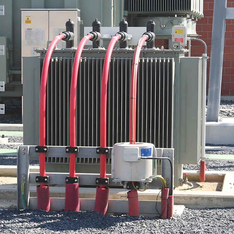
Z-type transformers, as a special grounding transformer with unique winding configurations, demonstrate distinctive advantages in power systems. This article provides an in-depth analysis of their technical features and offers a holistic solution covering selection, configuration, installation, commissioning, and maintenance to meet diverse application needs.
1. Core Advantages of Z-Type Transformers
1.1 Ultra-Low Zero-Sequence Impedance
Z-type transformers excel in low zero-sequence impedance (≈10Ω), making them ideal for small-current grounding systems. Their zigzag winding design cancels out zero-sequence flux in the core, allowing 90–100% arc suppression coil capacity (vs. 20% for conventional transformers).
1.2 Harmonic Suppression
The zigzag connection neutralizes third harmonics, ensuring near-sinusoidal phase voltages and improved power quality. During normal operation, they exhibit high positive/negative sequence impedance with minimal no-load losses.
1.3 Multifunctionality
Z-type transformers can serve dual roles as grounding and station service transformers, reducing infrastructure costs. They also enhance lightning protection by mitigating overvoltage risks from surge propagation.
2. Key Application Scenarios
2.1 Renewable Energy Integration
In wind/solar farms, Z-type transformers provide artificial neutral points for delta-connected systems, enabling relay protection and asymmetric load compensation.
2.2 Urban Cable Networks
For systems with capacitive currents >10A (3–10kV) or >30A (35kV+), Z-type transformers support arc suppression coils or resistors to suppress intermittent arcing overvoltages.
2.3 Industrial and Rail Systems
- Industrial grids: Balance loads, suppress harmonics, and protect equipment from fault currents.
- Rail transit: Mitigate stray currents by stabilizing rail-to-ground potentials (e.g., Shenzhen Metro reduced corrosion risks by 60%).
3. Configuration with Arc Suppression Coils & Grounding Resistors
3.1 Arc Suppression Coils
- Design: Use auto-tuning coils with damping resistors (≈12% of coil reactance) to limit resonance.
- Parameters: 35kV systems require 3.77–77.28Ω resistors; residual current ≤5A with ±5% detuning.
3.2 Grounding Resistors
- Formula: R=Up(2–3)ICR = \frac{U_p}{(2–3)I_C}R=(2–3)ICUp, where UpU_pUp= phase voltage, ICI_CIC = capacitive current.
- Typical values: 5–30Ω for 35kV systems (1000–2000A), 10–15Ω for 10kV systems (15–600A).
3.3 Protection & SCADA Integration
- Zero-sequence CTs monitor fault currents (e.g., 1000A threshold for 35kV systems).
- AI-driven SCADA systems enable millisecond fault response (e.g., Shanghai Metro’s 99.999% reliability).
Here is the professional English translation of the technical specifications table:
|
Application Scenario |
System Voltage Level |
Grounding Method |
Grounding Resistance / Arc Suppression Coil Configuration |
Zero-Sequence Current Protection Setting |
|
New Energy Grid Integration |
35kV |
Low-resistance grounding |
5-30Ω, Grounding current 1000-2000A |
Approx. 1000A, Operation time ≤1s |
|
Urban Cable Distribution Network |
10kV |
Arc suppression coil grounding |
Coil capacity = 90%-100% of main transformer capacity, |
Residual current ≤5A, |
|
Industrial Distribution Network |
6kV |
Low-resistance grounding |
Grounding resistance 10-15Ω, |
>15A, Operation time ≤5s |
|
Rail Transit System |
35kV |
Low-resistance grounding |
5-30Ω, Grounding current 1000-2000A |
Approx. 1000A, Operation time ≤1s |
4. Installation & Commissioning Guidelines
4.1 Pre-Installation Checks
- Verify civil works (e.g., embedded parts, drainage) and equipment integrity (e.g., insulation, bushings).
4.2 Wiring Options
- Option 1: Direct connection to main transformer (cost-effective but less reliable).
- Option 2: Separate bay with circuit breakers (higher reliability).
4.3 Testing Protocols
- Pre-commissioning: Measure DC resistance, insulation, and voltage ratio.
- Load Tests: Validate protection logic via simulated ground faults and monitor no-load noise for abnormalities.
5. Maintenance & Smart Monitoring
5.1 Routine Inspections
- Check grounding resistance (≤4Ω), insulation, and load balance to prevent neutral-line overloads.
5.2 IoT-Driven Predictive Maintenance
- Sensors (e.g., VBL12 triaxial sensors) monitor vibration, temperature, and tilt (ISO 10816 compliant).
- Cloud-based AI predicts faults 7 days in advance (e.g., averted $2M loss in a power plant).
5.3 Fault Diagnosis
- Address 100Hz vibrations (loose windings), neutral-point voltage >15% (system imbalance), or resistor failures.
6. Economic & Reliability Analysis
6.1 Cost-Benefit
- Initial costs are 15% higher than conventional transformers, but savings include:
- Dual functionality (grounding + station service).
- Reduced lightning damage and maintenance (30% lower annual costs).
- ROI: ~3 years in urban grid upgrades.
6.2 Reliability Metrics
- 40% higher system stability in cable networks.
- Predictive maintenance cuts downtime by 60%.
