• WD-G350 Integrated high frequency high voltage power supply
WD-G350 Integrated high frequency high voltage power supply
$4600.00
Model
HFHP-35
Basic info
Brand Wone
Model NO. WD-G350 Integrated high frequency high voltage power supply
Rated voltage AC220V+10%
Series WD-G350
Product Detail

Description

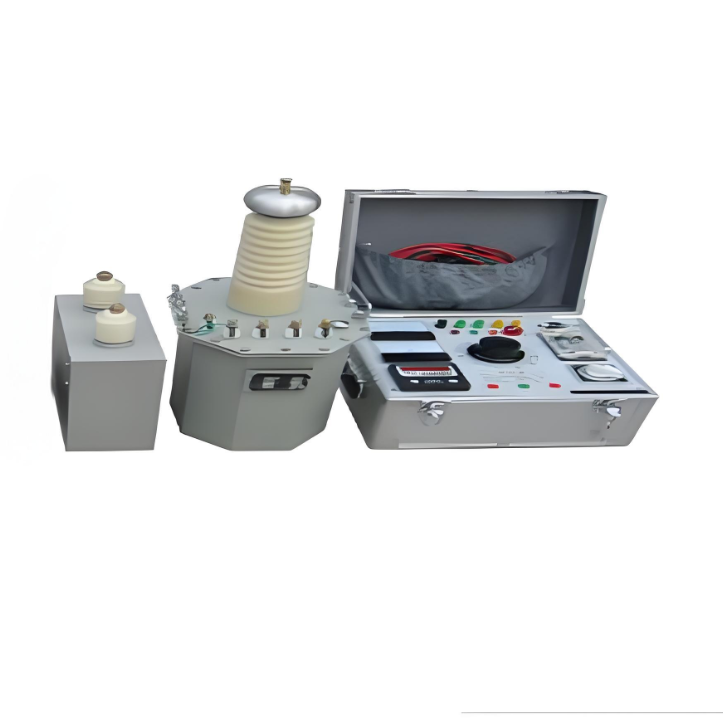
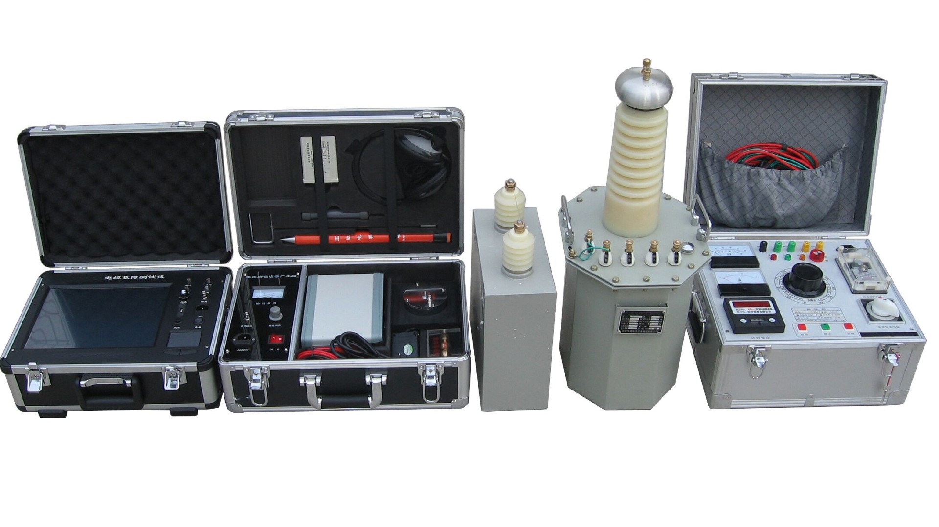
This product is mainly used for sampling impulse discharge of high-resistance fault waveform during fault testing of 35kV and below power cables and for impulse discharge when the fault point is accurately located. The sheath is used at precise points, and the burn-through capability can burn through the breakdown point in a short time and reduce the breakdown point resistance.

Feature

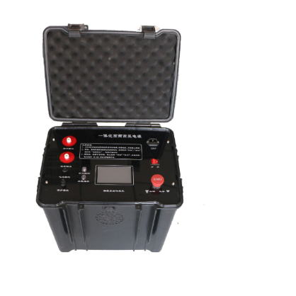
  • Integrated design, built-in capacitor, simple wiring.

  • Touch screen human-computer interaction, simple setting operation, intuitive and convenient display of instrument status.

  •  With voltage regulation, automatic voltage regulation and automatic protection functions.

  • The output high voltage has the function of single pulse and continuous pulse, respectively cooperate with the fault tester and the fixed point instrument to find the fault point.

  • The output high voltage has a DC output, which can be connected to an external ball gap for work, and the application is diversified.

  • Software controls vacuum shock spark discharge, self-adaptive discharge and pulse cycle.

  • With emergency stop button, automatic discharge function, automatic voltage reduction and discharge after emergency stop or shutdown, safe and reliable.

  • The continuous working time is not less than 6 hours, which meets the longest working time of the cable fault test.

  • Engineering chassis design, compact structure.

Specifications


Output mode pulse output/DC output
Output voltage  negative voltage, ≤35kV
Working current ≤40mA
Working mode ingle pulse/continuous pulse/DC output
Built-in capacitor 2.8uF/35kV
Discharge energy ≤1715J
Pulse period 3s~8s self-adaptive
Auto-discharge automatic discharge after shutdown
Working power supply power frequency 220V±10%
Display screen 800×480 resolution touch display
Working temperature  -10℃~40℃
Working humidity ≤80%
Altitude  ≤1000 meters
Dimensions 478(L)*370(W)*448(H) mm
Weight ≤28kg


Know your supplier
Wone
Main Categories
High voltage/Low voltage/Wire cable/Instrument meters/New energy/Tester/Production equipment/Generator/Electrical fittings/Integrated Electrical Equipment
Business Type
Design/Manufacture/Sales
Highest Annual Export (USD)
$50,000,000
Professional Experience
1 years
Workplace
65666m²m²
占位
占位
Related Products
Related Knowledges
Failure Analysis and Design Optimization of Conventional Grounding Transformers
I. Core Cause of Damage: Electrodynamic Impact (Complying with GB/T 1094.5 / IEC 60076-5)The direct cause of high-voltage winding end collapse is the instantaneous electrodynamic impact induced by short-circuit current. When a single-phase grounding fault occurs in the system (such as lightning overvoltage, insulation breakdown, etc.), the grounding transformer, as the fault current path, withstands high-amplitude and steep-rise-rate short-circuit currents. According to Ampère's force law
Felix Spark
06/12/2025
Analysis of Grounding Transformer Operational Behavior Under System Single-Phase-to-Ground Fault Conditions
1 Theoretical AnalysisIn distribution networks, grounding transformers serve two key roles: powering low - voltage loads and connecting arc - suppression coils at neutrals for grounding protection. Grounding faults, the most common distribution network fault, heavily impact transformers’ operating characteristics, causing sharp changes in electromagnetic parameters and status.To study transformers’ dynamic behaviors under single - phase grounding faults, build this model: Assume a tr
Felix Spark
06/12/2025
Design Calculations for Neutral Grounding Schemes and Grounding Transformer Sizing in Utility-Scale Solar PV Plants
1 Classification of Neutral Grounding Methods for Solar Photovoltaic Power StationsInfluenced by differences in voltage levels and grid structures across regions, the neutral grounding methods of power systems are mainly categorized into non-effective grounding and effective grounding. Non-effective grounding includes neutral grounding via arc suppression coils and neutral ungrounded systems, while effective grounding comprises neutral solid grounding and neutral grounding via resistors. The sel
Dyson
06/12/2025
Zero-Sequence Impedance Characterization of Dry-Type Grounding Transformer with ZN Connection
In a neutral-insulated three-phase power system, an earthing transformer provides an artificial neutral point, which can be solidly earthed or earthed via reactors/arc suppression coils. The ZNyn11 connection is typical, where zero-sequence magnetomotive forces in the inner/outer half-windings of the same core column cancel out, balancing fault currents in series windings and minimizing zero-sequence leakage flux/impedance.Zero-sequence impedance is critical: it determines fault current magnitud
Dyson
06/12/2025
Case Analysis on Maloperation of Grounding Transformer Overcurrent Protection Relay
The neutral grounding mode refers to the connection between the power system neutral point and ground. In China's 35 kV and below systems, common methods include ungrounded neutral, arc-suppression coil grounding, and small-resistance grounding. The ungrounded mode is widely used as it allows short-term operation during single-phase grounding faults, while small-resistance grounding has become mainstream for its fast fault removal and overvoltage limitation. Many substations install grounding tr
Felix Spark
06/12/2025
Discussion on the Design of Low Zero-Sequence Impedance Grounding Transformers
With the expansion of power system scale and the cableization process of urban power grids, the capacitive current in 6kV/10kV/35kV power grids has significantly increased (generally exceeding 10A). As power grids at this voltage level mostly adopt neutral ungrounded operation mode, and the distribution voltage side of main transformers is usually in delta connection, lacking a natural grounding point, the arc during ground faults cannot be reliably extinguished, necessitating the introduction o
Dyson
06/11/2025
×
Inquiry
Download
Experts Electrical is dedicated to serving the personnel in the global power industry.
Join Experts Electrical, not only can you discover power equipment and power knowledge, but also canhnd like - minded friends!
商品视频播放