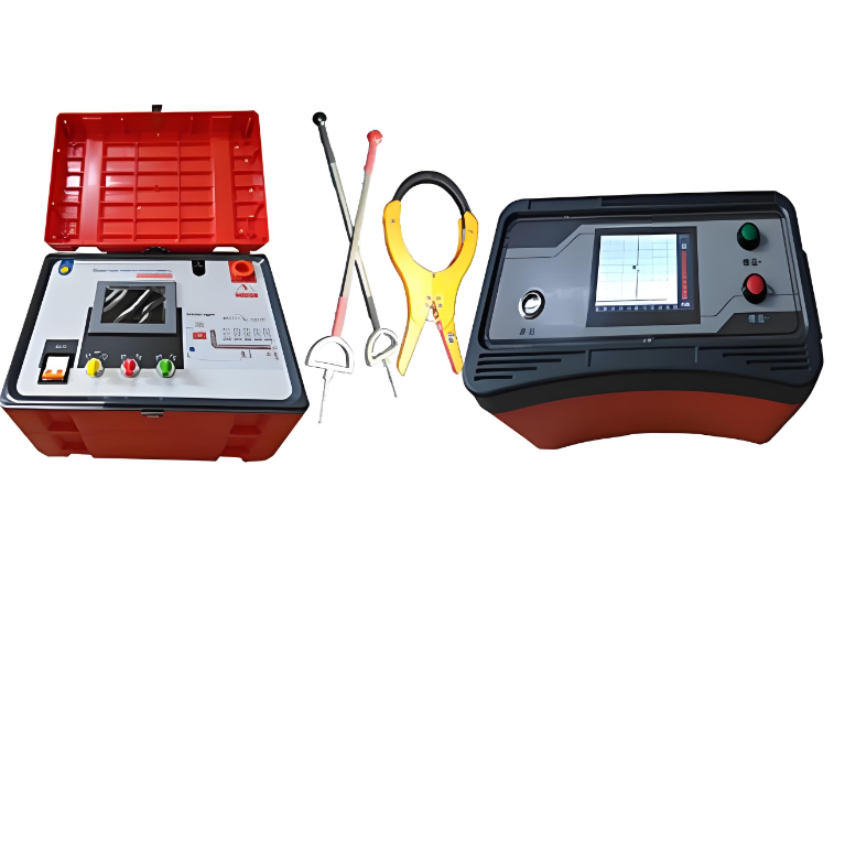
• WD-2137 Underground pipeline detector
  • WD-2137 Underground pipeline detector
  • WD-2137 Underground pipeline detector
WD-2137 Underground pipeline detector
$5000.00
Model
PT0-60
Basic info
Brand Wone
Model NO. WD-2137 Underground pipeline detector
Output Voltage 60V
Series WD-2137
Product Detail

Description

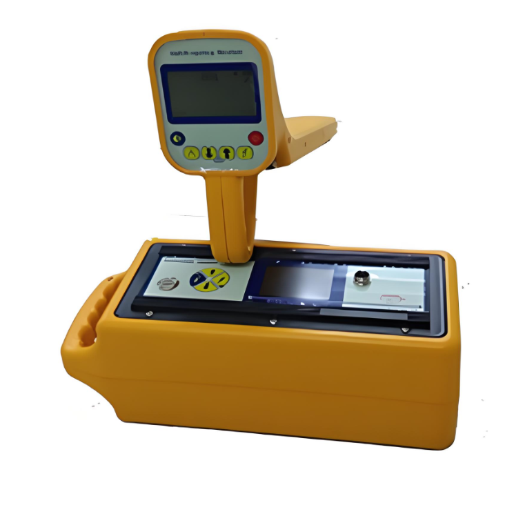
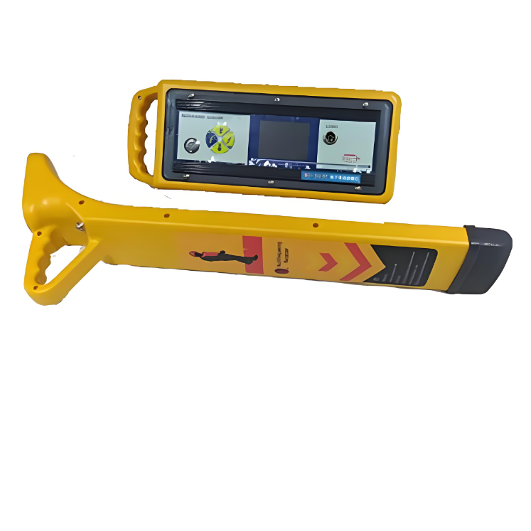
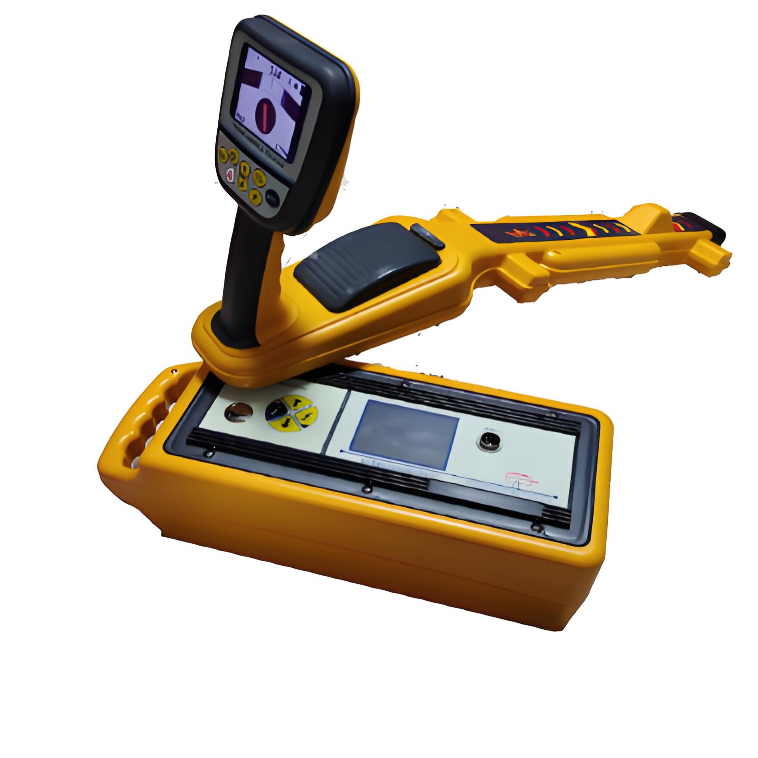
WD-2137 underground pipeline detector is a high-tech product designed based on the reflection principle and electromagnetic induction principle of electromagnetic waves in the transmission process, combined with digital filtering, wireless reception and software control.

Specifications

Transmitter technical parameters:

  •  Apply a specific frequency of positioning signal to the pipeline;

  • Output mode: induction mode, direct connection mode, and clamp mode;

  • Operating frequency: 577Hz, 815Hz, 8k Hz, 33 k Hz, 65.5kHz, 82k Hz, 133k Hz, three composite frequencies simultaneously output and the selected frequency custom;

  •  Output power: 10W;

  •  Output voltage: 60V;

  •  Maximum output current: 1A;

  •  Power supply: double power supply, lithium battery pack (energy saving and environmental protection);

  •  Continuous working hours: 12 hours at 1W; 8 hours at 5W; 5 hours at 10W;

  •  Ambient temperature: -20℃ -50℃.

Receiver technical parameters:

  • The receiver has two receiving modes, "basic" and "peripheral". When the mode is "A-frame" mode, the "peripheral" receiving mode can only be entered in the A-frame mode.

  •  Receiving frequency: Receive five kinds of sinusoidal AC signals of low frequency, intermediate frequency, high frequency, radio frequency and 50Hz.

  •  Receiving mode: crest method (horizontal coil), trough method (vertical coil), depth measurement (dual horizontal antenna), current measurement (dual horizontal antenna).

  •  Signal interface: digital size, trapezoidal grating length, sound priority three ways to prompt signal strength at the same time

  • Display interface: high-brightness LCD, supports working under strong sunlight, and backlighting to ensure normal work at night.

  •  Gain control: manual adjustment, dynamic range 000-100db.

  •  Probe length:

When the metal pipeline is directly connected, the maximum length is 15KM. .

When coupling metal pipelines, one coupling can measure 3Km, and multiple couplings are infinite.

When sensing metal pipelines, one sensing can measure 300m, and multiple sensing is infinite.

  • Depth measurement:

Direct reading detection depth, range 000-300cm.

80% method to measure the depth, range 000-300cm (coupling)  600cm (direct connection)

  •  Current measurement: direct reading current, range 000-999mA.

  •  Detection accuracy: ±2.5%+5cm (0-2m)

  •  Power supply: imported high-capacity 18650 lithium battery pack, charge and discharge 500 times.

  •  Standby time: more than 12 hours, power prompt.

  • Overheating and overcurrent: automatic protection.

  • Working temperature: -10℃—40℃.

  •  Dimension: 650×110×32 mm

  •  Weight: 1.6Kg


Know your supplier
Wone
Main Categories
High voltage/Low voltage/Wire cable/Instrument meters/New energy/Tester/Production equipment/Generator/Electrical fittings/Integrated Electrical Equipment
Business Type
Design/Manufacture/Sales
Highest Annual Export (USD)
$50,000,000
Professional Experience
1 years
Workplace
65666m²m²
占位
占位
Related Products
Related Knowledges
Failure Analysis and Design Optimization of Conventional Grounding Transformers
I. Core Cause of Damage: Electrodynamic Impact (Complying with GB/T 1094.5 / IEC 60076-5)The direct cause of high-voltage winding end collapse is the instantaneous electrodynamic impact induced by short-circuit current. When a single-phase grounding fault occurs in the system (such as lightning overvoltage, insulation breakdown, etc.), the grounding transformer, as the fault current path, withstands high-amplitude and steep-rise-rate short-circuit currents. According to Ampère's force law
Felix Spark
06/12/2025
Analysis of Grounding Transformer Operational Behavior Under System Single-Phase-to-Ground Fault Conditions
1 Theoretical AnalysisIn distribution networks, grounding transformers serve two key roles: powering low - voltage loads and connecting arc - suppression coils at neutrals for grounding protection. Grounding faults, the most common distribution network fault, heavily impact transformers’ operating characteristics, causing sharp changes in electromagnetic parameters and status.To study transformers’ dynamic behaviors under single - phase grounding faults, build this model: Assume a tr
Felix Spark
06/12/2025
Design Calculations for Neutral Grounding Schemes and Grounding Transformer Sizing in Utility-Scale Solar PV Plants
1 Classification of Neutral Grounding Methods for Solar Photovoltaic Power StationsInfluenced by differences in voltage levels and grid structures across regions, the neutral grounding methods of power systems are mainly categorized into non-effective grounding and effective grounding. Non-effective grounding includes neutral grounding via arc suppression coils and neutral ungrounded systems, while effective grounding comprises neutral solid grounding and neutral grounding via resistors. The sel
Dyson
06/12/2025
Zero-Sequence Impedance Characterization of Dry-Type Grounding Transformer with ZN Connection
In a neutral-insulated three-phase power system, an earthing transformer provides an artificial neutral point, which can be solidly earthed or earthed via reactors/arc suppression coils. The ZNyn11 connection is typical, where zero-sequence magnetomotive forces in the inner/outer half-windings of the same core column cancel out, balancing fault currents in series windings and minimizing zero-sequence leakage flux/impedance.Zero-sequence impedance is critical: it determines fault current magnitud
Dyson
06/12/2025
Case Analysis on Maloperation of Grounding Transformer Overcurrent Protection Relay
The neutral grounding mode refers to the connection between the power system neutral point and ground. In China's 35 kV and below systems, common methods include ungrounded neutral, arc-suppression coil grounding, and small-resistance grounding. The ungrounded mode is widely used as it allows short-term operation during single-phase grounding faults, while small-resistance grounding has become mainstream for its fast fault removal and overvoltage limitation. Many substations install grounding tr
Felix Spark
06/12/2025
Discussion on the Design of Low Zero-Sequence Impedance Grounding Transformers
With the expansion of power system scale and the cableization process of urban power grids, the capacitive current in 6kV/10kV/35kV power grids has significantly increased (generally exceeding 10A). As power grids at this voltage level mostly adopt neutral ungrounded operation mode, and the distribution voltage side of main transformers is usually in delta connection, lacking a natural grounding point, the arc during ground faults cannot be reliably extinguished, necessitating the introduction o
Dyson
06/11/2025
×
Inquiry
Download
Experts Electrical is dedicated to serving the personnel in the global power industry.
Join Experts Electrical, not only can you discover power equipment and power knowledge, but also canhnd like - minded friends!
商品视频播放