| Brand | Wone |
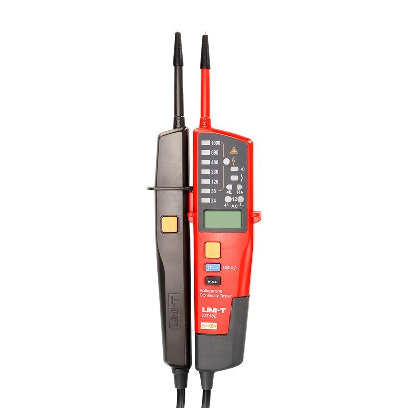
| Model NO. | UT18C Pocket Voltage And Continuity Testers 12V-690V LED AC/DC Voltage Indication Auto Range Voltmeter Voltage Tester |
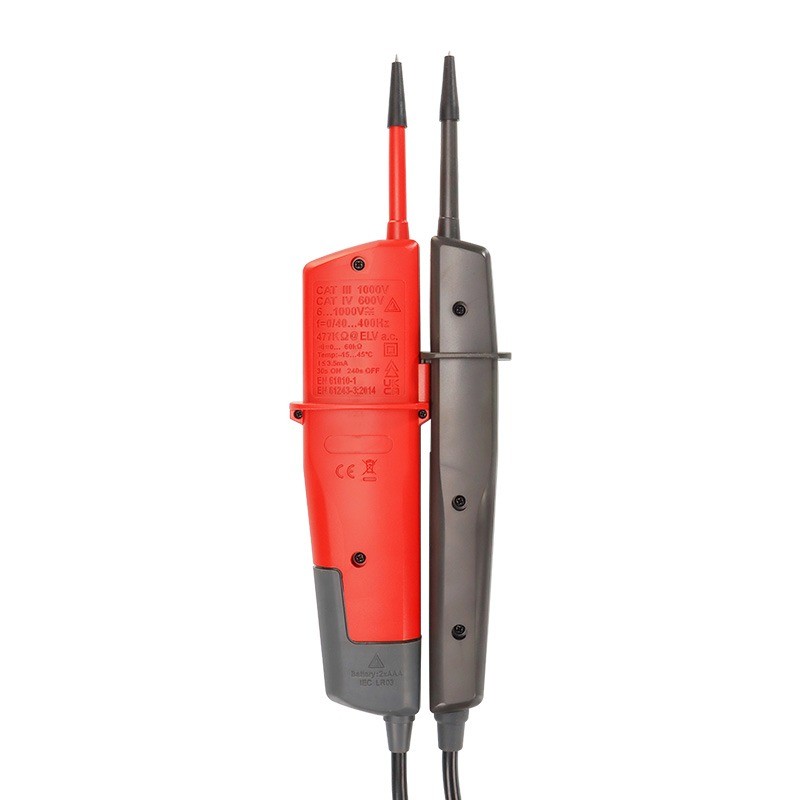
| Frequency range | 50Hz~400Hz |
| Voltage range | 562V±24V |
| Series | VCT18C |
Feature
Certifications: CE, UKCA, cETLus
RCD test (Operating voltage: 230V/50Hz~400Hz)
Polarity detection: Positive & Negative
Self-inspection: All LED or LCD
Exceed voltage (voltage range: 713V~788V)
Auto standby (standby current < 10μA)
Silent mode: All range
Work light
Low battery indication: around 2.5V
Specifications


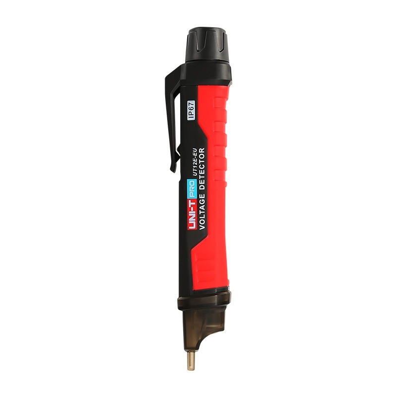
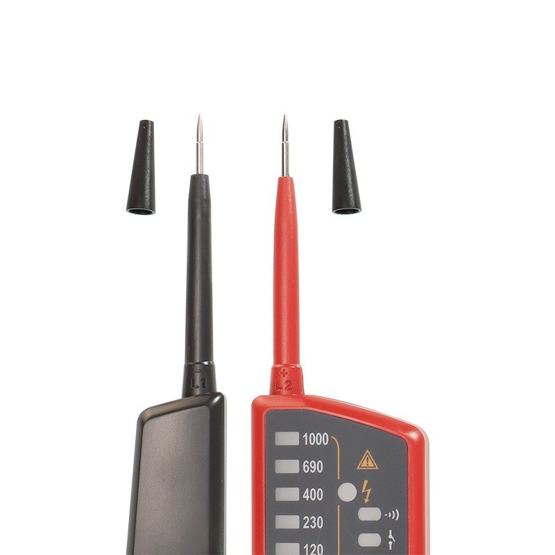
How does a voltage and continuity tester transmit signals?
Probe Contact:Voltage Measurement: Touch the red probe (positive) to the positive terminal of the circuit under test, and the black probe (negative) to the negative terminal or ground.
Continuity Test: Touch the two probes to two points in the circuit to check if there is conduction between these two points.
Signal Conduction:Voltage Signal: When the probe contacts the point under test in the circuit, the tester's internal circuit conducts the voltage signal from the circuit through the probe.
Resistance Signal: During a continuity test, the tester's internal circuit conducts the resistance signal between the two points in the circuit through the probes.