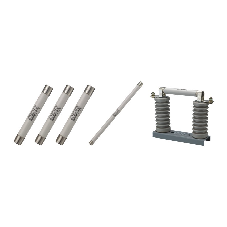
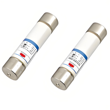
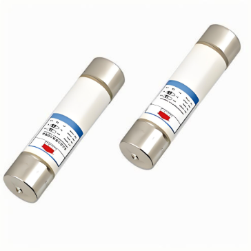
High Voltage Current-Limiting Fuse(For use in oil switchgear)
discuss personally
Model
| Brand | Wone |
| Model NO. | High Voltage Current-Limiting Fuse(For use in oil switchgear) |
| Rated voltage | 12kV |
| Rated normal current | 100A |
| Breaking capacity | 40kA |
| Series | Current-Limiting Fuse |
Characteristic brief:
Rated voltage from 3.6KV to 12KV.
Wide range of rated current from 6.3A to 250A.
Powerful pyrotechnic striker.
Unique tripe seal.
H.R.C.
Current-limiting.
Low power dissipation, low temperature rise.
Operation extremely quickly, high reliability.
Mainly used for back-up protection in transformers of American type.
Conforming to standards: GB15166.2 BS2692-1 / IEC60282-1.
Model illustration:

Technical Parameters:

External dimensions:

BS&DINtype H.V. fuse link cross section compared:(Unit:mm)


BS Type H.V Fuse Link Cross Section
What is the working principle of high-voltage current-limiting fuses (for oil switchgear)?
During normal operation, the high-voltage current-limiting fuse has a very low resistance, allowing the normal operating current to pass through without affecting the circuit. Essentially, it behaves like a regular conductor, permitting current to flow smoothly.
When an overload or short-circuit fault occurs in the circuit, causing the current to exceed the fuse's rated current, the fusible element begins to heat up. Due to the large magnitude of overcurrent or short-circuit current, the heating rate of the fusible element is rapid, and it reaches its melting point within a short time, leading to its immediate melting.
At the moment the fusible element melts, an arc is generated. At this point, the arc-quenching device activates. As previously mentioned, materials such as oil and possibly quartz sand are used to extinguish the arc during this process. Simultaneously, due to the current-limiting effect of the fuse, the amplitude of the fault current is restricted within a certain range, preventing it from increasing uncontrollably.