Single Phase Din Rail Electric Meter Mini Digital Wholesale kWh
$80.00
Model


| Brand | Wone |
| Model NO. | Single Phase Din Rail Electric Meter Mini Digital Wholesale kWh |
| Rated voltage | 230V |
| Rated normal current | 5(50)A |
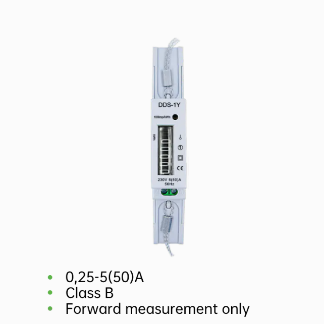
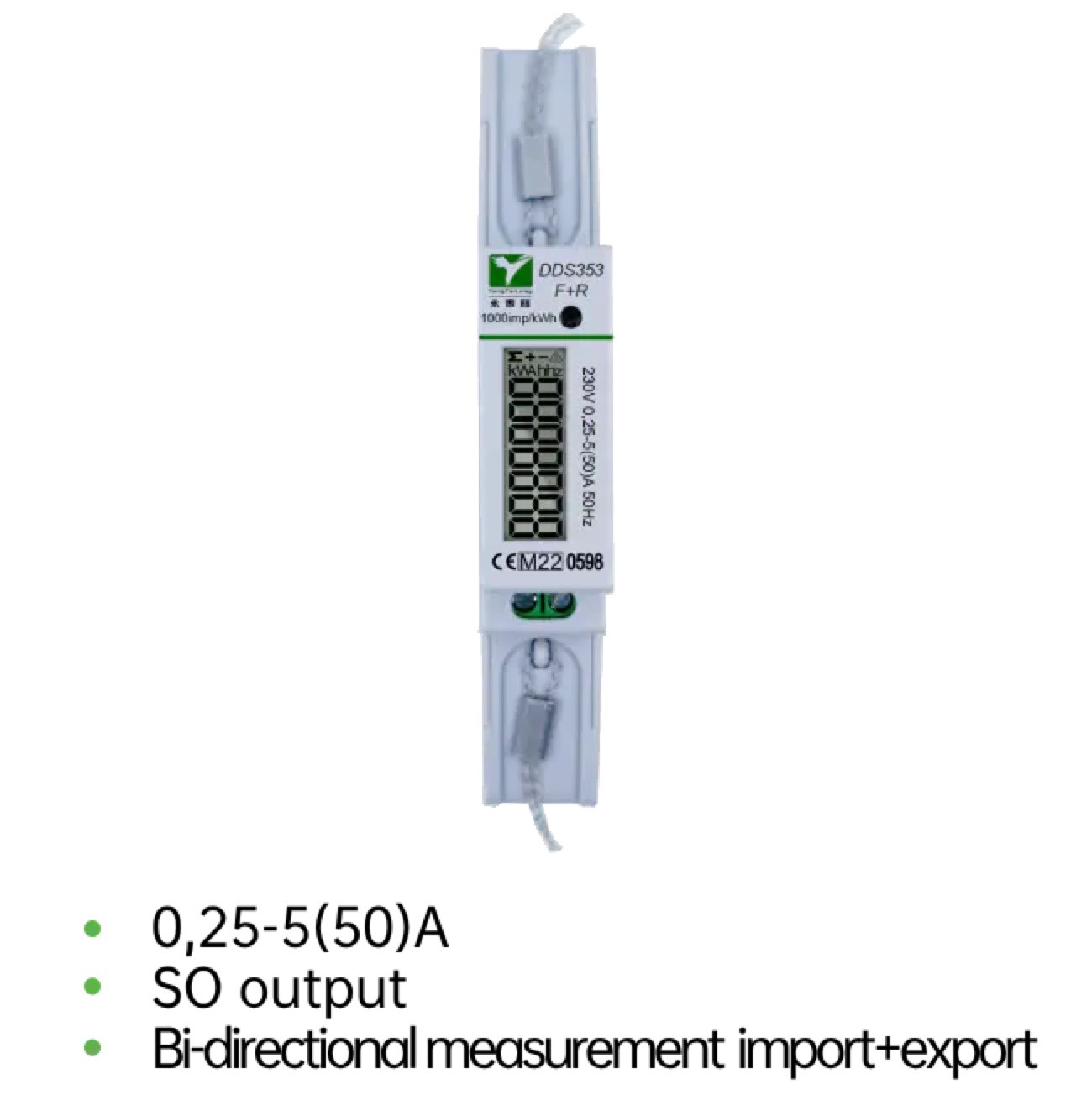
| Series | DDS353F+R |
Description
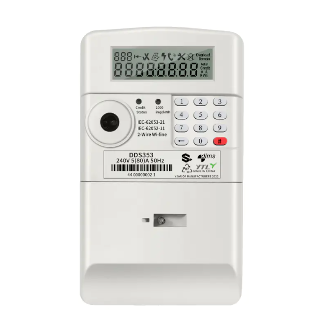
The DDS353 Series Digital Power Meter works directly connected to a maximum load 50A AC circuit.
This meter has been MID B&D Certified by SGS UK, proving both it’s accuracy and quality.
This certification allows this model to be used for any sub-billing applications.
Specifications
| Main |
|
|---|---|
| Range | DDS353F+R |
| Product or Componet Type | Energy meter |
| Country of origin | China |
| Complementary |
|
|---|---|
| Phase | Single Phase |
| Type of measurement | 1 = kWh total ( forward + reverse) 2 = kWh (forward energy [import]) 3 = kWh (reverse energy [export]) |
| Metering type | Measurement |
| Device Application | Solar Power Energy Charge |
| Accuracy class | Class 1.0S |
| Rated Current | 0,25-5(30)A,0,25-5(32)A,0,25-5(40)A, 0,25-5(45)A,0,25-5(50)A |
| Rated Voltage | 230V |
| Network Frequency | 50-60Hz |
| Technology Type | Electronic |
| Display Type | LCD display |
| Sampling rate | ------ |
| Maximum value measured | 99999.99kWh |
| Tariff input | ----------- |
| Communication port protocol | Modbus-RTU |
| Communication port support | RS485 |
| Local signalling | ------ |
| Number of inputs | ------- |
| Number of Outputs | -------------- |
| Output voltage | 230V |
| Mounting Mode | Clip-on |
| Mounting Support | DIN rail |
| Connections - terminals | ------- |
| Standards | EN50470-1/3 |
| Environment |
|
|---|---|
| IP degree of protection | IP40 front panel: conforming to IEC 60529 IP20 body: conforming to IEC 60529 |
| Relative humidity | 5…95 % 97 °F (36 °C) |
| Ambient air temperature for operation | -12…158 °F (-25…70 °C) - IEC |
| Ambient Air Temperature for Storage | -30…185 °F (-40…85 °C) |
| Operating altitude | < 9842.52 ft (3000 m) |
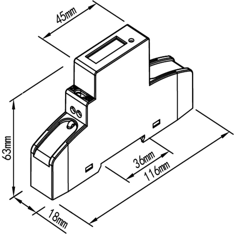
| Dimensions | 116mm*18mm*63mm |
| Packing Units |
|
|---|---|
| Unit Type of Package 1 | PCE |
| Number of Units in Package 1 | 1 |
| Package 1 Height | 50cm |
| Package 1 Width | 60cm |
| Package 1 Length | 70cm |
| Package 1 Weight | 1.000kg |
Dimensions

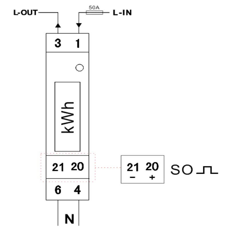
Diagram for installation