• 25-36kW Three Phase 3 MPPTs C&I Grid-tied Inverters
  • 25-36kW Three Phase 3 MPPTs C&I Grid-tied Inverters
25-36kW Three Phase 3 MPPTs C&I Grid-tied Inverters
discuss personally
Model
WN25K-MT
Basic info
Brand Wone
Model NO. 25-36kW Three Phase 3 MPPTs C&I Grid-tied Inverters
Max.Input Voltage 1100V
Max. Input Current per MPPT 30A
Number of MPP trackers 3
Nominal Output Voltage 400V
Max.Efficiency 98.8%
Series C&I Grid-tied Inverters
Product Detail

Description:

The three-phase inverter is ideal for commercial rooftop system solutions. The SMT series achieves maximum efficiency of 98.8% and features unique design highlights, including solid capacitors, fuse-free design, and optional Arc Fault Circuit Interrupter (AFCI) function. These new features ensure a longer lifespan and a higher safety level of operation, allowing for an improved user experience. With a compact design and weight of just 40 kg, the SMT series is more convenient to install. With a maximum DC input voltage of 1100V, a wider MPPT range for complex rooftops, and a start-up voltage of 180V, the SMT series guarantees an earlier generation of power and a longer working time to maximize long-term returns and profitability in safe operating conditions.

Feature:

Smart Control & Monitoring 

  • String level monitoring. 

  • Dynamic power export limit.

Optimal Generation for Higher Return

  • 98.8% Max. Efficiency.

  •  Up to 130% DC input oversizing & 110%.

 AC output overloading

  • Superb Safety & Reliability.

  • Optional Arc-fault circuit interrupter.

  •  Optional Type II SPD on both DC and AC.

Friendly & Thoughtful Design

  • 40kg compact design.

  • Power line communication optional.

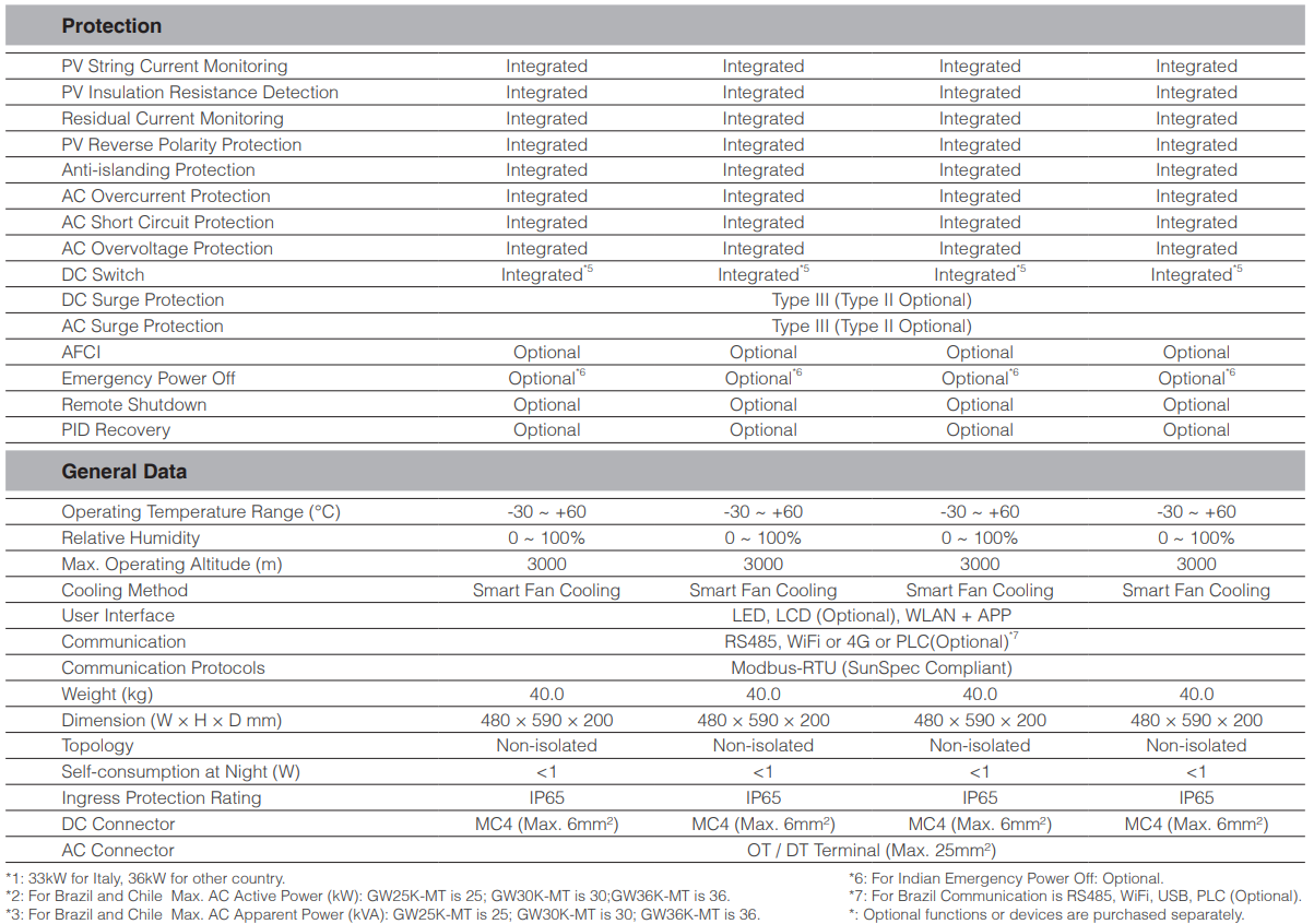
System Parameters:
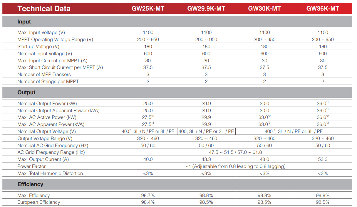

image.png

image.png

What is G&I grid-tied inverter?

Definition:
A grid-connected inverter is a device that converts direct current (DC) into alternating current (AC) and ensures that the output AC matches the frequency, phase, and voltage amplitude of the power grid. In this way, the converted electrical energy can be directly integrated into the power grid for use by households, enterprises, and the power grid itself.

Working Principle:

  • Input Circuit: The grid-connected inverter receives direct current from solar photovoltaic panels, wind turbines, or other DC power sources.

  • DC/AC Conversion: Through internal power electronic converters (such as inverter bridges), the direct current is converted into alternating current.

  • Synchronization Control: Through advanced control algorithms (such as Phase-Locked Loop, PLL), it ensures that the output alternating current is synchronized with the frequency, phase, and voltage amplitude of the power grid.

  • Output Circuit: The converted alternating current is fed to the power grid, and it is ensured that the output of the inverter complies with the power quality of the power grid.

Know your supplier
Wone
Main Categories
High voltage/Low voltage/Wire cable/Instrument meters/New energy/Tester/Production equipment/Generator/Electrical fittings/Integrated Electrical Equipment
Business Type
Design/Manufacture/Sales
Highest Annual Export (USD)
$50,000,000
Professional Experience
1 years
Workplace
65666m²m²
占位
占位
Related Products
Related Knowledges
What are the common failures in single-phase distribution transformers?
Single - phase distribution transformers, as crucial voltage transformation and power distribution equipment in the power system, are widely used in rural power grids, low - voltage residential areas, and areas with concentrated single - phase loads.With the continuous increase in the proportion of single - phase loads in the distribution network, the failure rate of single - phase transformers has also increased. Timely identification and handling of these faults are of great significance for e
Felix Spark
06/18/2025
Comprehensive Analysis of Single-Phase Distribution Transformer Technologies in Multiple Application Scenarios
Introduce the 10 kV line to the load center. Following “small capacity, dense points, short radius”, adopt the new single - phase distribution mode, featuring notable low - voltage line loss reduction, high power quality, and reliability. By comparing the economy and reliability of single - phase vs three - phase transformers in different scenarios, this paper analyzes their applicable scope and application suggestions.Single - phase transformers are classified by distribution mode:
Echo
06/18/2025
What are the technical features and applications of single-phase distribution transformers?
1 Technical Features of Single - phase TransformersFrom the operation practice of foreign distribution networks, it is known that single - phase transformers are quite widely applied. Compared with three - phase transformers, they have unique advantages, which are specifically reflected as follows:1.1 Simple StructureThis characteristic makes that, when using the same materials, for single - phase transformers with the same capacity, their no - load losses are lower than those of three - phase t
Echo
06/17/2025
Application Analysis of High-Voltage Single-Phase Distribution Transformers in Power Distribution Networks
1. Safety Hazards in Substation Operation1.1Transformer FailuresTransformers are critical substation equipment and maintenance focal points. Loose/defective components often cause malfunctions, while internal damage (e.g., oil tank impurities/water/bubbles) triggers partial discharge, risking major losses during outages.1.2 Overvoltage RisksOutdoor overvoltage threatens equipment. Lightning-induced impulse currents alter transformer electromagnetic energy, and circuit breaker misoperations cause
Echo
06/17/2025
Prototype Development of 20 kV Single-Phase Distribution Transformer
1. Design of 20 kV Single - phase Distribution Transformer20 kV distribution systems usually adopt cable lines or mixed cable - overhead line networks, and the neutral point is mostly grounded through a small resistance. When a single - phase grounding occurs, there will be no problem that the phase voltage will rise by more than √3 times as in the case of a single - phase fault in a 10 kV system. Therefore, the single - phase distribution transformer of the 20 kV system can adopt the type
Dyson
06/17/2025
Single-Phase Transformer with High Lightning Impulse Withstand Capability
1 IntroductionTo ensure the safe operation of railways and reduce the risk of lightning damage to railway telecommunication control systems, the author has specially researched and designed a single - phase series transformer with a relatively high impulse voltage withstand level, with the model number D10 - 1.2 - 30/10. This transformer is equipped with an oil conservator and adopts a fully sealed structure (it can also be designed as a dry - type structure according to actual needs). This seri
Dyson
06/17/2025
×
Inquiry
Download
Experts Electrical is dedicated to serving the personnel in the global power industry.
Join Experts Electrical, not only can you discover power equipment and power knowledge, but also canhnd like - minded friends!
商品视频播放