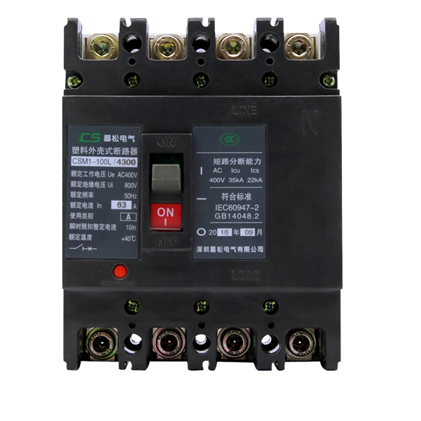
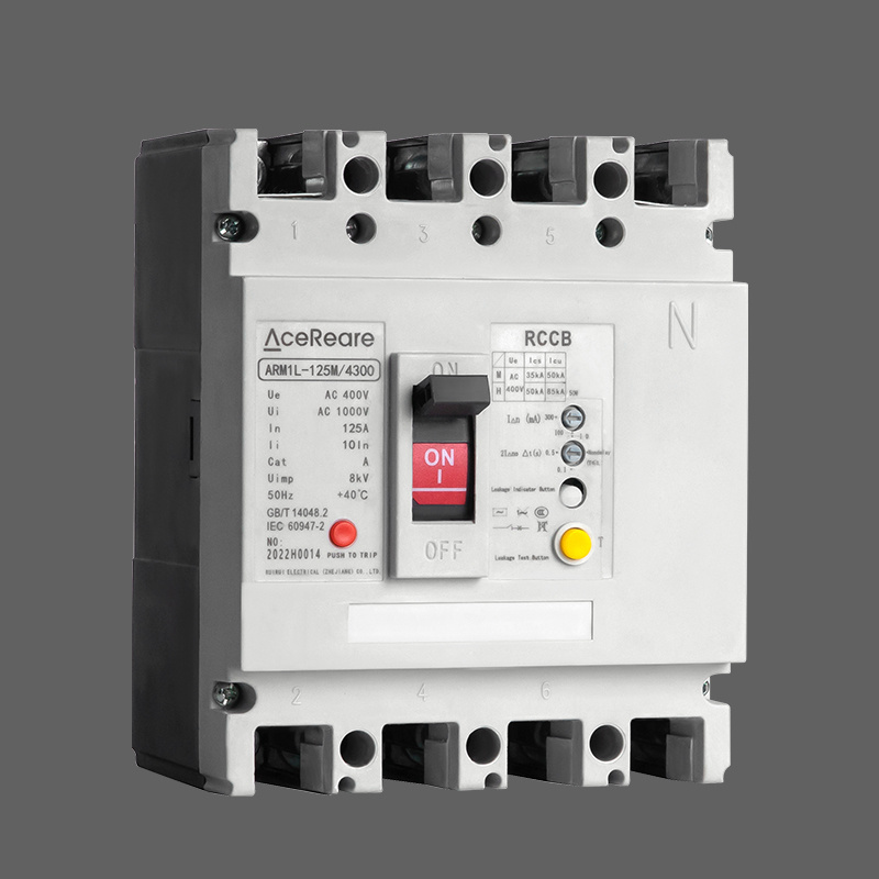
• 125A Residual Current ProtectedMolded Case Circuit Breaker
125A Residual Current ProtectedMolded Case Circuit Breaker
$150.00
Model
ARM1L-400/125
Basic info
Brand Wone
Model NO. Residual Current ProtectedMolded Case Circuit Breaker
Rated voltage 400V
Rated normal current 125A
Series Arm1L
Product Detail

Description

Residual current circuit breaker, mainly applicable to AC 50Hz, rated voltage 400V, rated current up to 800A in the distribution network, used to provide indirect contact protection to people, can also be used to prevent fire hazards caused by equipment insulation damage, resulting in ground fault current, and can be used to distribute electrical energy and protect the line and power supply equipment overload and short circuit, but also as the line of infrequent conversion and motor Infrequent switching and motor starting. Conventional leakage protection module with residual current protection circuit breaker work power sampling for two-phase, this series of circuit breakers for three-phase, if the lack of a phase, circuit breaker leakage protection module can still work normally; rated residual action current and maximum disconnection time according to the actual situation on site adjustable; when the phase voltage is reduced to 50V, leakage protection module can still work normally

Basic Info.

image.png

External dimensions

image.png


Environmental requirement


1,The surrounding air temperature state is: -5ºC~+40ºC

2,The altitude of the installation site does not exceed 2000m

3,The relative humidity of the air at the installation site does not exceed 50% at the highest temperature of +40ºC, and can have a higher relative humidity at lower temperatures, such as up to 90% at 20ºC. Special measures should be taken for the occasional condensation due to temperature changes.

4,The pollution level is 3

5, wet and hot band type (TH type) circuit breakers through GB/T2423.4, GB/T2423.18 test requirements, can withstand the effects of humid air, salt spray, oil mist, mold.

6,The circuit breaker should be installed in a place where there is no danger of explosion and no conductive dust, not enough to corrode the metal and destroy the insulation

7, the circuit breaker should be installed in a place where there is no rain or snow intrusion

8,Operating conditions: the circuit breaker passes the test requirements of GB/T 2423.1 and GB/T2423.2, the surrounding air temperature can be as low as -25ºC (ARM1DC/ARM3DC/ARM6DC can provide temperature as low as -40ºC, consult our company), as high as +70ºC (more than 40ºC reduced capacity use, see the technical information in the attached sample)

Product show


image.png


Know your supplier
Wone
Main Categories
High voltage/Low voltage/Wire cable/Instrument meters/New energy/Tester/Production equipment/Generator/Electrical fittings/Integrated Electrical Equipment
Business Type
Design/Manufacture/Sales
Highest Annual Export (USD)
$50,000,000
Professional Experience
1 years
Workplace
65666m²m²
占位
占位
Related Products
Related Knowledges
Failure Analysis and Design Optimization of Conventional Grounding Transformers
I. Core Cause of Damage: Electrodynamic Impact (Complying with GB/T 1094.5 / IEC 60076-5)The direct cause of high-voltage winding end collapse is the instantaneous electrodynamic impact induced by short-circuit current. When a single-phase grounding fault occurs in the system (such as lightning overvoltage, insulation breakdown, etc.), the grounding transformer, as the fault current path, withstands high-amplitude and steep-rise-rate short-circuit currents. According to Ampère's force law
Felix Spark
06/12/2025
Analysis of Grounding Transformer Operational Behavior Under System Single-Phase-to-Ground Fault Conditions
1 Theoretical AnalysisIn distribution networks, grounding transformers serve two key roles: powering low - voltage loads and connecting arc - suppression coils at neutrals for grounding protection. Grounding faults, the most common distribution network fault, heavily impact transformers’ operating characteristics, causing sharp changes in electromagnetic parameters and status.To study transformers’ dynamic behaviors under single - phase grounding faults, build this model: Assume a tr
Felix Spark
06/12/2025
Design Calculations for Neutral Grounding Schemes and Grounding Transformer Sizing in Utility-Scale Solar PV Plants
1 Classification of Neutral Grounding Methods for Solar Photovoltaic Power StationsInfluenced by differences in voltage levels and grid structures across regions, the neutral grounding methods of power systems are mainly categorized into non-effective grounding and effective grounding. Non-effective grounding includes neutral grounding via arc suppression coils and neutral ungrounded systems, while effective grounding comprises neutral solid grounding and neutral grounding via resistors. The sel
Dyson
06/12/2025
Zero-Sequence Impedance Characterization of Dry-Type Grounding Transformer with ZN Connection
In a neutral-insulated three-phase power system, an earthing transformer provides an artificial neutral point, which can be solidly earthed or earthed via reactors/arc suppression coils. The ZNyn11 connection is typical, where zero-sequence magnetomotive forces in the inner/outer half-windings of the same core column cancel out, balancing fault currents in series windings and minimizing zero-sequence leakage flux/impedance.Zero-sequence impedance is critical: it determines fault current magnitud
Dyson
06/12/2025
Case Analysis on Maloperation of Grounding Transformer Overcurrent Protection Relay
The neutral grounding mode refers to the connection between the power system neutral point and ground. In China's 35 kV and below systems, common methods include ungrounded neutral, arc-suppression coil grounding, and small-resistance grounding. The ungrounded mode is widely used as it allows short-term operation during single-phase grounding faults, while small-resistance grounding has become mainstream for its fast fault removal and overvoltage limitation. Many substations install grounding tr
Felix Spark
06/12/2025
Discussion on the Design of Low Zero-Sequence Impedance Grounding Transformers
With the expansion of power system scale and the cableization process of urban power grids, the capacitive current in 6kV/10kV/35kV power grids has significantly increased (generally exceeding 10A). As power grids at this voltage level mostly adopt neutral ungrounded operation mode, and the distribution voltage side of main transformers is usually in delta connection, lacking a natural grounding point, the arc during ground faults cannot be reliably extinguished, necessitating the introduction o
Dyson
06/11/2025
×
Inquiry
Download
Experts Electrical is dedicated to serving the personnel in the global power industry.
Join Experts Electrical, not only can you discover power equipment and power knowledge, but also canhnd like - minded friends!
商品视频播放