What does the testing of photovoltaic transformers involve?

Oliver Watts
06/27/2025

1. Specificities and Testing Requirements of Photovoltaic Transformers
As a new energy systems technician, I recognize photovoltaic transformers' unique design and application traits: Inverter - output AC carries abundant 5th/7th - order odd harmonics, with PCC harmonic current distortion reaching 1.8% (higher voltage distortion under low load), causing winding overheating and accelerated insulation aging. Photovoltaic systems use TN - S grounding, requiring reliable N - phase output from the secondary side to avoid short circuits. Environmentally, they must withstand 60°C desert heat, coastal salt spray, and industrial EMI.
These specifics dictate testing uniqueness: Beyond conventional DC resistance, voltage ratio, insulation, and withstand voltage tests, add harmonic detection (Fluke F435 for THD), temperature rise monitoring (infrared imagers), grounding system checks (four - terminal method for ≤0.1Ω contact resistance), and short - circuit impedance testing. The core aim is ensuring safe operation in power electronic environments while preventing harmonic, thermal, and grounding - related risks.
2. Conventional Testing Items and Tool Selection for Photovoltaic Transformers
2.1 DC Resistance Test
This key test identifies inter - turn short circuits or loose connections in windings. The four - terminal method is used to eliminate line resistance interference, with procedures including power-off discharge, winding cleaning, temperature measurement, current selection (1A/10A), and temperature correction. The ZSCZ - 8900 DC resistance tester (accuracy: 0.2%±2μΩ, resolution: 0.1μΩ) meets high - precision requirements. Measured values must be compared with standards/historical data; significant deviations may indicate faults - as seen in a case where poor winding contact was detected via DC resistance testing and later repaired.
2.2 Voltage Ratio Test
This verifies whether winding turns ratios align with design specifications to ensure stable voltage output under load. The dual - voltmeter method calculates ratios by measuring primary/secondary voltages under no - load conditions, while the voltage ratio bridge method offers higher precision. For instance, a voltage imbalance in the low - voltage output of an 800V/400V transformer, caused by a high - voltage side open circuit, was identified through voltage ratio testing.
2.3 Insulation Performance Test
  • Insulation Resistance Test: Using an MI - 2094H megohmmeter, measure insulation resistance between windings and between windings and the core (required ≥300MΩ).
  • Withstand Voltage Test: Apply 2× rated voltage for 60 minutes to check for breakdown. Ensure power is off, disconnected from live equipment, and surfaces are clean before testing.
2.4 Short - Circuit Impedance Test
The volt - ampere method evaluates short - circuit tolerance: one side is shorted, and a test voltage is applied to the other side to drive rated current through windings, measured by a CS - 8 impedance tester. A change >±2% from the factory value may indicate winding deformation. Note: Test current should be controlled at 0.5% - 1% of rated current to avoid waveform distortion.
2.5 Temperature Rise Test
After full - load operation, measure temperatures of windings, core, and casing using thermometers or infrared thermometers. Temperature rises should be ≤60K for oil - immersed transformers and ≤75K for dry - type transformers. A dry - type transformer operating in a 60°C environment that maintained a temperature rise within 65K extended its service life effectively.
2.6 Grounding System Test
The four - terminal method measures grounding continuity to avoid misjudgments from the two - terminal method. Common faults include rusted connections or plastic washer misuse, requiring regular inspection. Four - terminal ground resistance testers ensure measurements meet the 0.1Ω standard.
2.7 Harmonic Detection
A unique test for photovoltaic systems, using Fluke F435 at the PCC to detect harmonics up to the 50th order (focusing on 5th/7th orders). Results must comply with GB/T 14549 - 93, providing data for equipment optimization.
3. On - site Testing Procedures and Safety Specifications for Photovoltaic Transformers
3.1 Pre - testing Preparation
Develop detailed plans specifying project information, testing items, and equipment lists (including high - precision power analyzers, power quality testers, infrared thermal imagers, etc.). Check equipment integrity and power voltage (220V±10%), and monitor environmental conditions - such as irradiance ≥700W/m², irradiance variation <2% in the preceding 5 minutes, no strong winds or clouds - to ensure test accuracy.
3.2 Electrical Connection Inspection
Use a phase volt - ampere meter to verify inverter output polarity matches the transformer's primary corresponding terminal, preventing circulating current losses. Inspect cable connections for tightness. For oil - immersed transformers, check oil level and color; for dry - type transformers, verify cooling fans operate normally.
3.3 Insulation Resistance Test
With power off, use a megohmmeter to test high/low - voltage windings and grounding, recording 1 - minute stable values. A sudden resistance drop indicates insulation issues. Detailed test reports must be compiled post - testing.
3.4 AC Withstand Voltage Test
Connect the withstand voltage device's output to test points, set parameters to 2× rated voltage, gradually increase voltage while monitoring for breakdown, and maintain for 60 minutes before reducing voltage.
3.5 Load Test
Measure output voltage, current, and power under full - load operation to calculate efficiency and voltage regulation rate, while monitoring temperature rise. Increase load current gradually and record parameter changes for analysis.
3.6 Short - Circuit Impedance Test
Apply voltage to the high - voltage side with the low - voltage side shorted (using wires with sufficient cross - section). Control test current at 0.5% - 1% of rated value and correct results for temperature (75°C for oil - immersed, 120°C for dry - type) to avoid misjudging winding deformation.
3.7 Harmonic Detection
Use a power quality analyzer at the PCC to monitor odd - order harmonic content and calculate THD, ensuring compliance with national standards for safe operation in harmonic environments.
Oliver Watts

Hey! I'm Oliver Watts, an electrical engineer in Inspection and Testing. With years of hands - on experience, I ensure electrical systems meet top safety and performance standards. Using advanced gear, I conduct diverse tests, easily spotting issues in both large - scale industrial and small - scale commercial setups. I love teaming up, sharing knowledge, and keeping up with industry regs. Also, I'm skilled at data analysis with software. If you're into electrical inspection or just want to chat engineering, reach out. Let's connect and explore!

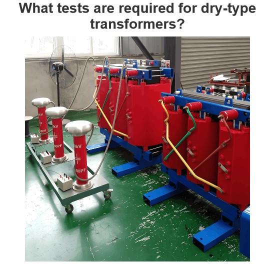
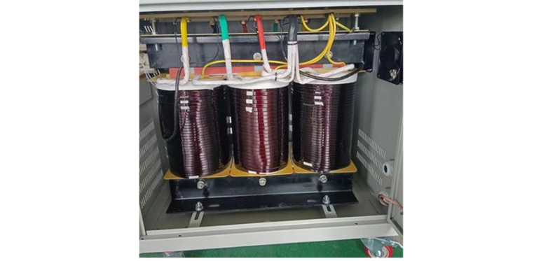
What tests are required for dry-type transformers?
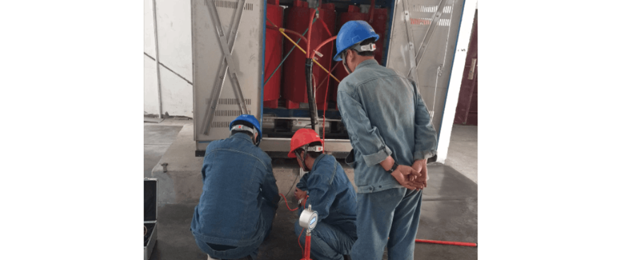
1 Pre - commissioning InspectionAs a front - line tester, before formally commissioning a dry - type transformer, I need to carry out a comprehensive and systematic inspection. First, I conduct a visual inspection of the transformer body and its accessories, carefully checking for mechanical damage or deformation. Then, I check whether the leads of the high - and low - voltage windings are firmly connected and whether the bolt tightening torque meets the standard requirements (usually 40 - 60N&m
Oliver Watts
07/01/2025
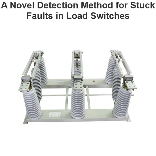
A Novel Detection Method for Stuck Faults in Load Switches
In recent years, as distribution automation advances, load switches see wider use in distribution lines. Yet, mechanical - failure - induced accidents are on the rise, burdening line operation and maintenance.Poor mechanical performance is the main cause of switch faults. Many scholars study large - scale switchgear operation, using methods like coil current detection, vibration signal analysis, switch travel testing, ultrasonic flaw detection, and infrared thermometry. Motor - current - based s
Oliver Watts
06/30/2025
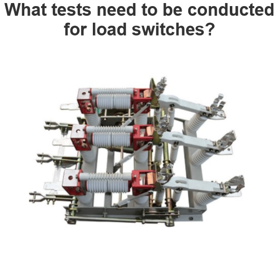
What tests need to be conducted for load switches?
As a technician with years of on-site experience in power testing, I understand the importance and complexity of load switch testing. Below, I combine practical work experience to elaborate on the full process of load switch testing, from testing items and methods to equipment and procedural specifications.I. Routine Electrical Performance Testing(1) Loop Resistance TestLoop resistance is a core indicator for evaluating a load switch's conductivity. I strictly follow GB/T 3804 and GB 1984 standa
Oliver Watts
06/28/2025
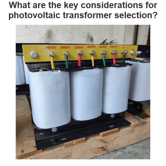
What are the key considerations for photovoltaic transformer selection?
Sizing Principles and Technical Parameters of Photovoltaic TransformersSizing photovoltaic transformers requires a comprehensive consideration of multiple factors, includingcapacity matching, voltage ratio selection, short - circuit impedance setting, insulation class determination, and thermal design optimization. The key sizing principles are as follows:(I) Capacity Matching: Fundamental for Load BearingCapacity matching is thecore prerequisitein sizing photovoltaic transformers. It requires a
Echo
06/27/2025
Inquiry
Download
Experts Electrical is dedicated to serving the personnel in the global power industry.
Join Experts Electrical, not only can you discover power equipment and power knowledge, but also canhnd like - minded friends!